Intelligence BuildoutMethodology

Fabric — complete text edition

Volume V / Text edition

Fabric

Networks + storage + orchestration. 15 spreads and 30 pages, with the complete evidence-linked content. No JavaScript is required.

Volume V

Fabric

Networks + storage + orchestration · 30 pages

The connective system that turns racks into a coordinated cluster: links, switches, optics, storage, runtimes, schedulers, security boundaries, and the operators who keep useful work moving.

01

The movement machine

Begin with the traffic: tensors, parameters, training data, and checkpoints must arrive before compute can proceed.

Spread 01 / The real workload

Orientation

An AI cluster is a data-movement machine

Installed compute becomes productive only when every dependency reaches it on time.

A model does not run on arithmetic alone. Training samples must stream from storage, parameters must be available in memory, partial results must cross links, and updates must be synchronized before the next step can begin. The fabric is the complete delivery system for that motion: on-board buses, scale-up links, rack networks, campus fiber, storage paths, drivers, collective libraries, schedulers, and the operational controls that hold them together.

This changes how the buildout should be read. A powerful accelerator waiting for a packet is an expensive idle asset. A fast switch attached to a poorly shaped workload is equally wasted. Effective capacity therefore emerges from the slowest recurring boundary between compute, memory, network, and storage—not from the largest component specification printed on a product sheet.

Reader's rule: Follow the byte, not the brand. Ask where data starts, which boundaries it crosses, how often it moves, and what happens when one path fails.
An inference request creates several traffic classes
  1. Admit and route— Authenticate the request, apply tenant policy, select a model replica, and preserve an end-to-end deadline.
  2. Load and prefill— Make weights and adapters resident, process prompt tokens, and create key-value state near the chosen workers.
  3. Transfer and decode— Move or reuse state, schedule token generation, and prevent queueing from defeating interactive latency.
  4. Stream and observe— Return tokens while recording latency, cache use, errors, retries, energy, and tenant attribution.
Fabric begins wherever one component must wait for another.

Traffic classes

Not every byte has the same deadline

The network simultaneously serves flows with very different shapes and consequences.

Training produces several kinds of traffic. Dataset reads are often large and sequential; collective operations exchange tightly timed fragments among workers; checkpoint writes arrive in bursts; control messages are small but latency-sensitive; observability streams must remain available during failure. Inference adds request fan-out, cache movement, and response deadlines. Treating these flows as one average bandwidth number hides the events that actually stop useful work.

Design starts by mapping each traffic class to a service objective, route, and failure behavior. Critical collectives may need predictable lossless transport, while background data staging can absorb delay. Checkpoints need sustained write performance and rapid restore, not merely peak throughput. The goal is not to make every path maximal. It is to reserve the right capacity, in the right tier, for the moment the application cannot wait.

Traffic has different operational consequences
FlowDominant needFailure consequence
CollectivesPredictable latencyWorkers wait together
Dataset ingestSustained throughputAccelerators starve
CheckpointsBurst writes + restoreProgress is exposed
Control planeReachabilityScheduling and recovery degrade
Measure movement at the user-visible boundary
MetricWhat it revealsCommon blind spot
Time to first tokenAdmission, queue, route, load, and prefill delayReporting only steady decode speed
Inter-token latencyDecode scheduling and memory serviceAverages hiding tail pauses
Request throughputCompleted service under an arrival patternBatching away the latency objective
Transfer bytesKV, weights, storage, and replica movementCounting only payload tokens
Wall energyFull serving-system costSubstituting component TDP

Spread 02 / Distance has a price

Hierarchy

A byte travels through nested neighborhoods

Locality is the first network optimization.

Data can sit in accelerator memory, host memory, a peer device, pooled memory, local flash, a nearby storage appliance, or a remote facility. Each step outward usually adds protocol work, shared contention, energy, and recovery complexity. Software placement decisions therefore become physical infrastructure decisions: keeping a tensor local can avoid links, switches, optical conversions, and queueing that no later tuning can erase.

Architects describe a hierarchy because no single medium can provide maximum capacity, minimum latency, broad reach, and low cost at once. Device links serve the nearest exchanges. PCIe attaches devices and hosts. CXL extends coherent and pooled-memory patterns. Network fabrics connect racks and pods. Storage networks protect durable state. Good systems keep the most frequent exchanges inside the smallest reliable neighborhood while preserving paths for sharing and recovery.

Read the path from near to far
  1. Place— Keep hot state near the processor that repeatedly consumes it.
  2. Attach— Use device and host interconnects for local I/O and coordination.
  3. Pool— Share selected resources when utilization gains justify added distance.
  4. Persist— Move recoverable state into a storage tier built for durability.
Fabric domains have different contracts
On-node
Processor, accelerator, memory, storage, and host links whose failures and locality are usually managed as one server boundary.
Scale-up
A tightly coupled accelerator domain optimized for peer access and collectives, often with strict membership and topology assumptions.
Scale-out
Routed connectivity among nodes or racks that adds reach, tenancy, queueing, congestion control, and replaceable network paths.
Storage and WAN
Durable and long-distance paths with different consistency, recovery, security, latency, and operational ownership from compute fabrics.

Interfaces

Standards define boundaries, not outcomes

A link rate is only one layer of the delivered path.

PCI Express defines a widely used device-attachment foundation, and its sixth generation raises raw signaling capacity substantially. CXL builds on that physical ecosystem to support coherent device and memory use cases, including sharing and pooling. These standards matter because they let processors, accelerators, memory devices, switches, firmware, and operating systems negotiate common behavior across organizational boundaries.

Yet an interface specification cannot guarantee application throughput. Encoding, protocol overhead, lane count, topology, switching, memory controllers, software queues, thermal limits, and contention all intervene. Procurement should separate three layers: what the standard permits, what a component vendor specifies, and what the complete workload sustains. That discipline prevents an impressive edge-link number from being mistaken for end-to-end model performance.

PCIe 6.0 raw data rate per lane; delivered throughput depends on the full implementation.
64 GT/s
Evidence class
fact
Claim
claim-pcie6-bandwidth
Context
The specification also describes up to 256 GB/s bidirectionally for an x16 link.
Place workloads against the physical hierarchy
  • Translate each parallel group into required peers, memory, endpoints, bandwidth, latency, and failure tolerance before requesting generic accelerator counts.
  • Prefer compact placement when synchronization dominates, but retain enough route and power diversity that one shared component does not erase the whole allocation.
  • Reserve topology explicitly during admission; partial placement can fragment the cluster, deadlock gang-scheduled work, or strand devices that are healthy individually.
  • Re-evaluate placement after failures and maintenance because the logical inventory may remain constant while the usable physical graph changes.

Spread 03 / Scale up

Tight coupling

Make many accelerators behave like one

Scale-up fabric serves the exchanges that cannot tolerate a distant network.

Large layers and fast collective operations can require more memory and compute than one accelerator contains. Scale-up links connect accelerators across a board, tray, or rack with high bandwidth and low latency so software can partition work while preserving rapid exchange. The topology becomes part of the computer architecture: which devices are direct neighbors affects how tensors are sliced, reduced, broadcast, and reassembled.

This domain includes proprietary systems as well as emerging consortium standards. UALink 1.0, for example, defines a scale-up fabric intended to connect large accelerator groups. Its importance is architectural rather than merely numerical: a common interface can broaden the component ecosystem, but deployed performance will still depend on switches, cabling, protocol behavior, memory systems, collective software, and the physical boundaries chosen by each implementation.

Terms of the topology
Scale up
Couple accelerators closely enough to participate in one large computational domain.
Collective
A coordinated operation—such as reduce, gather, or broadcast—performed across workers.
Hop
One traversal between network elements; additional hops can add delay and contention.
A collective is a distributed critical path
  1. Partition— Divide tensors or state into chunks whose size and order fit the algorithm and link topology.
  2. Schedule— Choose rings, trees, or other routes while coordinating computation, memory access, and communication streams.
  3. Transport— Move every chunk through endpoints and switches without one slow peer or congested path setting the tail.
  4. Complete— Deliver a consistent result to all required participants before the dependent workload phase can advance.

Design test

Topology must match the model

The fastest fabric can still be wrong for the communication pattern.

A topology distributes bandwidth unevenly by design. Fully connected neighborhoods favor direct exchange but become difficult to expand. Switched topologies increase reach and flexibility while adding shared resources and failure points. Hierarchical designs mirror physical packaging and rack boundaries, but a model partition that repeatedly crosses those boundaries can turn every training step into a network penalty.

Engineers therefore co-design placement and communication. They measure message sizes, collective frequency, synchronization points, and sensitivity to stragglers, then map parallel groups onto the physical graph. Resilience matters too: removing one link or switch should produce a known reduction in capacity rather than an opaque collapse. The objective is predictable useful throughput under realistic workload and failure conditions, not a maximum synthetic result on an empty network.

Maximum accelerator scale described for the UALink 1.0 scale-up fabric.
1,024
Evidence class
fact
Claim
claim-ualink-scale
Context
A specification ceiling is not evidence that every implementation or workload scales efficiently to that size.
Connectivity is not collective health: A link can remain up while retries, lane degradation, thermal throttling, queue imbalance, or one slow endpoint expands collective tail latency. Acceptance should run simultaneous communication and computation, vary message sizes, and remove a member or path. Record application-step time alongside link counters so a reroute that preserves reachability but violates the workload objective is classified as degraded capacity rather than success.

Spread 04 / Scale out

Cluster fabric

Connect racks without creating a traffic jam

Scale-out networks expand the failure domain and the scheduling domain at the same time.

Beyond the nearest accelerator domain, scale-out networks connect servers, racks, pods, storage systems, and management services. InfiniBand and Ethernet with RoCE are common approaches for high-performance clusters, while conventional Ethernet remains central to storage, service, and control networks. The choice includes far more than a protocol name: adapters, switches, optics, congestion control, routing, telemetry, security, and operating practice must work as one system.

At this scale, synchronized workers can amplify small imbalances. A congested path delays one participant; the collective waits; upstream compute stops; queues then shift elsewhere. Good design supplies path diversity and controls contention before it becomes global. It also separates traffic classes where their failure modes differ, so a management event or checkpoint burst does not unexpectedly block the fabric carrying the most time-sensitive model exchange.

Questions before choosing a fabric
  • Which collectives dominate the target workloads?
  • What oversubscription is acceptable at each tier?
  • How are loss, congestion, and misbehaving endpoints contained?
  • Can operations identify a degraded path before jobs fail?
Scale-out topology is an economic and failure decision
QuestionEvidence to retain
How many stages?Hop distribution, latency tail, switch count, optics, and power
How much oversubscription?Workload traffic matrix and simultaneous worst credible demand
Which failure domains?Route diversity across switches, power, rooms, controls, and maintenance
How is growth added?Reserved ports, fibers, space, power, addressing, and compatible generations
Who shares links?Tenant policy, fairness, isolation, accounting, and service objectives

Capacity

Switch silicon is the beginning of a system

Aggregate capacity must survive ports, optics, routes, and real packet behavior.

Modern switch chips expose extraordinary aggregate throughput, allowing a network designer to connect many high-rate ports within one device. That density can reduce tiers and power per transported bit, but it concentrates heat, signal-integrity demands, and operational impact. The switch package must be fed by board traces, connectors, transceivers, fiber, firmware, and control software that are each qualified for the intended rate.

A vendor specification describes silicon capability under defined conditions; it does not describe delivered application performance. Port breakout, forward-error correction, packet size, buffering, routing, congestion, failures, and topology all consume or redirect capacity. The meaningful metric is how quickly the complete cluster finishes work while preserving recovery margin. That requires workload replay and failure testing, not arithmetic based solely on the switch data sheet.

Switching capacity specified for Broadcom's Tomahawk 6 Ethernet switch chip.
102.4 Tb/s
Evidence class
vendor_spec
Claim
claim-switch-throughput
Context
Delivered throughput depends on topology, ports, optics, protocol, and congestion behavior.

The revenue series is an audited supplier signal for one company's data-center networking business. It is not total global network spending, installed fabric value, switch-only revenue, or a count of deployed links. Product mix includes NVIDIA's networking portfolio and can change between periods. Use it to show commercial scale and growth while keeping procurement quantities, market share, customer capex, and future demand outside the claim.Claim

NVIDIA Data Center networking revenue

Audited fiscal-year revenue reported by NVIDIA for its Data Center networking specialized market.
Data Center networking revenueUSD billions
View chart values
NVIDIA Data Center networking revenue — underlying values in USD billions
CategoryData Center networking revenue
FY2025$12.99 USD billions
FY2026$31.38 USD billions

AUDITED SUPPLIER REVENUE — NVIDIA-specific and not total network capex, market size, installed capacity, or a forward projection.

02

The physical signal path

Inspect every conversion between processor, board, cable, optic, switch, and distant endpoint.

Spread 05 / Endpoints

Network edge

NICs and DPUs shape the traffic

The fabric begins before a packet reaches the first cable.

A network interface translates between host or accelerator memory and the external fabric. It queues work, applies protocol functions, moves data through direct-memory-access paths, and reports health to the operating system. SmartNICs and DPUs can take on transport, virtualization, security, or storage tasks that would otherwise consume host processors. These capabilities create headroom only when their software and isolation boundaries are designed deliberately.

Endpoint behavior often determines whether nominal fabric capacity is usable. Queue depths, packet pacing, placement of buffers, PCIe attachment, NUMA locality, firmware, and driver versions can create limits long before a switch is full. The endpoint must also fail safely: a stuck queue, bad cable, or unhealthy adapter should be visible and quarantined without corrupting a job or flooding shared links.

Transmit path
  1. Prepare— The runtime identifies buffers and posts communication work.
  2. Move— The adapter reads memory and constructs the transport operation.
  3. Shape— Queues, pacing, and congestion controls govern entry to the fabric.
  4. Observe— Counters and traces expose retries, loss, stalls, and route health.
Endpoint work before a packet moves
Queue mapping
Assigns traffic to hardware and software queues whose depth, affinity, priority, and service policy shape latency and fairness.
Memory registration
Authorizes direct access to selected memory regions and binds transport performance to page placement, pinning, protection, and lifecycle control.
Offload
Moves protocol, security, storage, or collective work onto endpoint hardware, saving host cycles while adding firmware and observability dependencies.

Boundary

Attachment bandwidth is shared bandwidth

Devices compete across local I/O before they compete in the network.

A server may attach accelerators, NICs, storage devices, and management components through a finite set of processor lanes and switches. Diagramming the front-panel ports without the internal PCIe graph can conceal oversubscription, cross-socket traffic, or a shared upstream link. Retimers and switches extend reach and connectivity, but they also add components, firmware, power, and points of failure.

Qualification should reproduce the intended concurrency: network transfers while storage writes checkpoints, accelerators exchange data, and telemetry continues. Engineers then compare interface counters with application progress to find the first sustained bottleneck. This systems view matters because a headline PCIe rate describes an interface generation, not the lane allocation, board layout, topology, or application efficiency of a particular server.

Inspection boundary: Trace the path from accelerator memory to the wire. Any unlabeled switch, retimer, socket crossing, or firmware layer is an unpriced dependency.
RDMA and accelerator access need explicit isolation
  • Bind device access, memory keys, queue pairs, and service identities to the tenant and workload lifecycle; stale authorization must not survive reassignment.
  • Segment management, storage, collective, and tenant traffic where their trust, loss tolerance, or recovery behavior differs rather than relying on one flat high-speed plane.
  • Test malformed requests, revoked credentials, exhausted queues, retry storms, and device reset so fast paths cannot bypass admission, accounting, or containment.
  • Expose endpoint firmware and configuration in attestation and change control because an offload device can enforce or violate the intended boundary.

Spread 06 / Copper and light

Physical media

Every meter changes the design

Electrical reach is convenient; optical reach carries a conversion tax.

Short links can remain electrical through board traces, passive copper, or active electrical cables. As data rates and distance rise, attenuation, crosstalk, connector loss, and equalization become harder to manage. Optical links convert electrical signals into light for longer reaches and higher port density, then convert them back at the destination. The conversion adds transceivers, lasers, control electronics, heat, and manufacturing dependencies.

Media selection is therefore a reach-and-system decision. Copper can reduce cost and optical components within a rack, but bulk and routing may become limiting. Pluggable optics simplify service but place heat at the switch face. Co-packaged approaches may improve electrical reach while changing repair boundaries. Fiber itself needs correct type, polarity, bend radius, cleaning, labeling, and spare strategy. A fabric is only as reliable as these apparently passive details.

SerDes
Circuits that serialize parallel data for transmission and recover it at the receiver.
Transceiver
A module that sends and receives signals, often converting between electrical and optical domains.
Insertion loss
Signal energy lost as a path crosses traces, connectors, cables, and other interfaces.
Choose media by the whole link budget
DomainDominant constraintsEvidence status to show
Inside systemReach, connector density, loss, crosstalk, mechanicsImplemented vendor specification
Rack and rowCable handling, airflow, replaceability, optics powerQualified product and installed test
Data centerFiber plant, patching, latency, redundancy, operationsDesigned route plus acceptance trace
Metro or DCICoherent optics, spectrum, amplification, protection, encryptionStandard envelope plus achieved route

Documentary plate

The abstract link becomes field work

Fiber capacity depends on civil routes, skilled installation, and disciplined records.

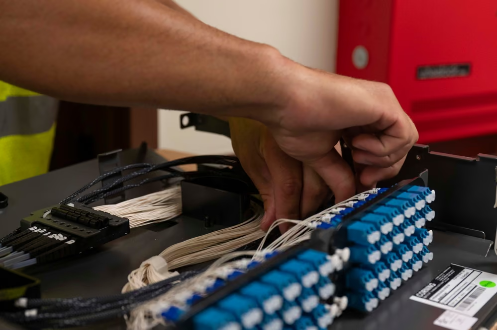
Cluster diagrams reduce connectivity to lines, but deployed fiber is handled, pulled, spliced, tested, patched, cleaned, and documented by people. Outside a building it may share ducts and rights-of-way; inside, it travels through trays and panels that must remain accessible during expansion. Route diversity is real only when supposedly separate paths do not converge in one trench, entrance, room, or maintenance event.

This documentary image shows fiber construction at a military installation, not an AI data-center network. It is included to make the physical dependency visible: high-rate digital links ultimately rely on ordinary civil work, protected pathways, and verification in the field. An AI campus inherits the same need to know where each strand runs and which cuts or closures can isolate it.

A network technician connecting fiber-optic cables to a rack-mounted termination panel.

A technician works on a fiber infrastructure project at Joint Base Pearl Harbor-Hickam.

Context image of fiber deployment; it does not depict a hyperscale AI cluster or imply endorsement by the source agency.DVIDS marks the item public domain. It illustrates physical fiber work, not a hyperscale AI-cluster fabric. The appearance of U.S. Department of War (DoW) visual information does not imply or constitute DoW endorsement. Individuals' publicity and privacy rights are not waived.U.S. Air Force photo by SrA Melody Bordeaux, via DVIDS, public domain.Original sourceU.S. government work / public domain
Operate optics as a measured chain
  1. Budget— Allocate transmitter, receiver, connector, splice, fiber, aging, temperature, repair, and engineering margin before procurement.
  2. Install— Inspect and clean connectors, verify polarity and route, record serials, then test the completed channel rather than components alone.
  3. Trend— Watch optical power, errors, temperature, retries, and maintenance history so degradation is found before an outage.
  4. Replace— Preserve failed parts and traces, confirm compatibility, retest the path, and update inventory and topology records.

Spread 07 / Routes and patching

Cable plant

Topology must survive the room

A logical path becomes thousands of physical decisions.

Port maps become switch locations, rack elevations, patch panels, fiber trunks, copper bundles, overhead trays, underfloor routes, labels, and slack management. Density changes the mechanics: cable bulk can block airflow, short bend radii can damage optical performance, and an inaccessible connector can extend repair time. Designers must preserve service paths while fitting power, coolant, and network infrastructure into the same constrained volume.

Documentation is part of the system. A database should link every logical port to its physical endpoints, route, optic, and test history. Moves and replacements must update that record. Without this discipline, a redundant topology slowly decays into unknown shared risks. Expansion planning also needs spare fibers, ports, tray capacity, and entry paths; otherwise the next compute block may require disruptive construction inside an operating hall.

The cable-plant ledger
  • Endpoint, port, medium, length, and approved optic
  • Physical route and shared-risk group
  • Installation and acceptance-test results
  • Reserved capacity, maintenance history, and current owner
Prove route diversity physically and logically
  • Trace paths through ports, line cards, chassis, power feeds, cable trays, patch panels, rooms, building entrances, ducts, carriers, and control systems.
  • Treat maintenance as a failure source: two paths are not independent when one permit, technician action, configuration push, or drain procedure affects both.
  • Test convergence with realistic state and traffic; reachability restored after a long pause may still violate training, checkpoint, or inference objectives.
  • Keep the designed graph, installed graph, discovered graph, and scheduler-visible graph reconciled after every repair and expansion.

Documentary plate

Routes are infrastructure, not decoration

The neat schematic exists only if physical work is controlled.

Structured pathways reduce accidental damage and make growth legible. They separate media where required, preserve bend limits, maintain clearances, and give technicians a repeatable way to reach the right connection. Poor routing turns routine repair into an outage risk and can undermine cooling by obstructing planned air or service spaces. The operational standard should be inspectable at a glance and verifiable in records.

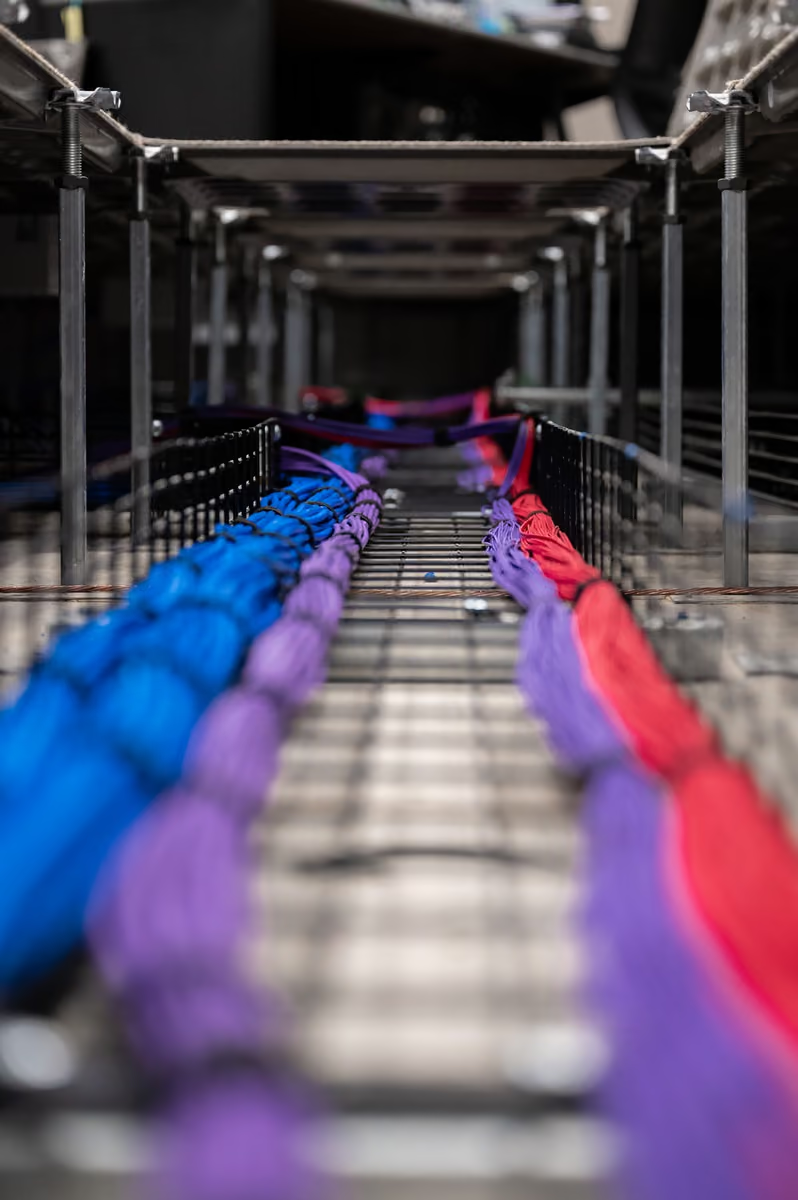
The photograph is a contextual view of routed communications infrastructure, not a claim about the architecture or performance of a specific AI installation. Its value is evidentiary: the digital fabric has weight, radius, connectors, and maintenance access. Those constraints must be included in rack design, construction schedules, spares, and commissioning—not discovered after high-value systems arrive on site.

Bundles of color-coded fiber-optic cable routed beneath a raised operations-room floor.

Installed communications cabling illustrates the physical pathways behind a logical network.

Representative infrastructure image; the pictured system is not identified here as an AI training network.DVIDS marks the item public domain. The installation shows physical routing discipline, not a training-cluster topology. The appearance of U.S. Department of War (DoW) visual information does not imply or constitute DoW endorsement. Individuals' publicity and privacy rights are not waived.U.S. Air Force photo by A1C Xavier Romero, via DVIDS, public domain.Original sourceU.S. government work / public domain
WAN and DCI add policy to distance
BoundaryDecision
ReachUse the implemented route loss and equipment, not only a standards maximum
LatencyBudget propagation, equipment, queues, encryption, and protection switching
SecurityAuthenticate endpoints, encrypt where required, and isolate management and tenant paths
ResilienceDeclare protection model, shared-risk groups, restoration priority, and tested recovery time
CapacityReserve headroom for failure, replication, checkpoint bursts, growth, and other users

Spread 08 / Congestion and topology

Shared capacity

Congestion is coordinated waiting

Synchronized applications can turn a local queue into a cluster-wide pause.

Network congestion occurs when offered traffic exceeds a path or destination's immediate service capacity. Buffers absorb short bursts, but sustained imbalance creates queueing, drops, retransmission, or explicit backpressure. AI collectives are unusually sensitive because many workers communicate in phases. One slow sender or crowded link can hold an entire group at a barrier, converting a small network event into broad accelerator idleness.

Control mechanisms must operate together across endpoints and switches. Routing spreads flows, pacing shapes bursts, congestion signaling asks senders to slow, and admission policies keep background work from overwhelming critical paths. Each mechanism can also interact badly with another if settings are copied without workload evidence. Testing should include synchronized incast, failed links, mixed message sizes, and storage bursts—not only uniform traffic under ideal conditions.

From symptom to cause
  1. Detect— Correlate job stalls with queue, retry, and link-health telemetry.
  2. Locate— Identify the shared path, destination, or synchronized sender group.
  3. Contain— Reroute, pace, isolate, or reschedule without spreading the event.
  4. Correct— Change placement, capacity, or policy and replay the workload.
Congestion symptoms are not causes
Incast
Many senders converge on one receiver or link, exhausting buffers faster than the destination can drain them.
Head-of-line blocking
A stalled flow delays unrelated traffic that shares a queue even when another onward path remains available.
Hot spot
Traffic or route selection concentrates load on a subset of endpoints or links while nominal aggregate capacity remains idle elsewhere.
Congestion spreading
Retries, pause behavior, or upstream queues propagate one bottleneck into parts of the fabric that were not originally overloaded.

Failure domains

Design the degraded state first

Redundancy matters only when recovery is understood and exercised.

A second link does not automatically create resilience. It may share a line card, switch, cable tray, power feed, control plane, software defect, or maintenance procedure with the first. Architects group components by shared risk and model what remains when each group disappears. The degraded topology must still provide enough connectivity for selected jobs to finish, checkpoint, or move safely.

This work connects physical and software domains. Routing must converge without long blackouts, schedulers must understand which resources remain mutually reachable, and collective libraries must avoid repeatedly selecting a damaged path. Operators need explicit thresholds for draining a node, rerouting traffic, or terminating a job. A predictable smaller cluster is often more valuable than a nominally redundant cluster that fails in surprising ways.

Boundary condition: High availability is not the count of duplicate boxes. It is the verified ability to preserve useful service after a defined shared-risk group is removed.
Mitigate without hiding the victim
  1. Observe— Capture queue occupancy, drops, marks, pauses, retries, route distribution, and workload phase with aligned timestamps.
  2. Attribute— Identify senders, receiver, tenant, collective, storage event, or failure route creating the sustained bottleneck.
  3. Control— Apply pacing, admission, queue policy, rerouting, placement, or capacity changes at the narrowest effective boundary.
  4. Verify fairness— Confirm the fix restores application progress without shifting loss or latency onto another tenant or traffic class.
03

Data, memory, and recovery

Keep training data moving, preserve progress, and expose the failure boundaries hidden behind storage capacity.

Spread 09 / The data pipeline

Storage path

Feed the cluster before it asks

Storage performance is a pipeline from durable media to accelerator memory.

Training data may begin in an object store or archive, pass through metadata services and parallel file systems, stage onto local flash, enter host memory, and finally reach accelerator memory. NVMe standardizes a host-controller interface for non-volatile memory across transports such as PCI Express, TCP, and Fibre Channel; it defines an interface, not an end-to-end storage-performance guarantee. Each tier still serves a different balance of capacity, throughput, latency, durability, and cost. The pipeline must prepare data fast enough that compute never sees the slowest durable tier directly during a critical step.Claim

Dataset format and software access patterns matter as much as drives. Many tiny files can overload metadata services; uneven sharding can make one worker finish late; insufficient prefetch creates bubbles; repeated transformations consume host processors. Designers model samples per second and burst behavior end to end, then place caches where they reduce recurring traffic without making provenance, eviction, or recovery unmanageable.

A prepared-data path
  1. Persist— Keep authoritative data in a durable, governed tier.
  2. Stage— Move the next working set near the scheduled compute.
  3. Transform— Decode and batch data without starving the accelerator.
  4. Verify— Track identity and integrity across cache and format changes.
Storage tiers should be compared by responsibility
TierPrimary roleFailure or operating boundary
Node-local flashFast staging, cache, or burst absorptionEviction, node loss, wear, and scheduler locality
Parallel filesystemShared high-throughput working dataMetadata scaling, contention, quotas, and purge policy
Object or key-arrayDurable datasets and application objectsConsistency, namespace, request rate, and egress path
ArchiveLong-retention source and recovery copyRecall time, media handling, integrity, and restore workflow

Throughput

Capacity is not feeding rate

A full storage system can still leave the most expensive devices idle.

Petabytes describe how much can be retained, not how quickly a synchronized training job can consume it. Delivered performance depends on media, controllers, network interfaces, metadata, file layout, client concurrency, caches, and the distribution of requests. Benchmarking should use the same record sizes, transformations, worker counts, and contention expected in production rather than a vendor's ideal sequential test.

The storage plane also carries writes: logs, metrics, artifacts, model outputs, and checkpoints. Reads and writes can collide at predictable moments, so capacity planning must reserve bandwidth for recovery and operational traffic. A design that reaches full read rate only by disabling durability or excluding checkpoint bursts does not meet the actual workload. Productive compute requires a balanced path in both directions.

Storage questions beyond raw capacity
LayerQuestion
MetadataCan all workers discover and open data concurrently?
Data pathIs throughput sustained at the workload's record sizes?
Write pathCan checkpoints land without collapsing reads?
RecoveryCan state be restored inside the operational objective?

These bars compare facility-stated capacities from three public research systems. They are not like-for-like offers: namespace, usable-versus-raw treatment, media mix, redundancy, access model, and system generation differ. Capacity also does not measure throughput, IOPS, metadata service, checkpoint completion, or restore time. The values provide documentary scale references; architecture decisions still require workload-shaped tests and a separate account of the tier actually feeding compute.Claim

Facility-stated storage capacity references

Published capacity figures for Perlmutter all-flash scratch, Aurora DAOS, and the Orion filesystem capacity tier.
Facility-stated capacityPB
View chart values
Facility-stated storage capacity references — underlying values in PB
CategoryFacility-stated capacity
Perlmutter44 PB
Aurora DAOS230 PB
Orion679 PB

FACILITY-STATED CAPACITY — different systems and tier semantics; not measured workload performance, market supply, or a like-for-like procurement comparison.

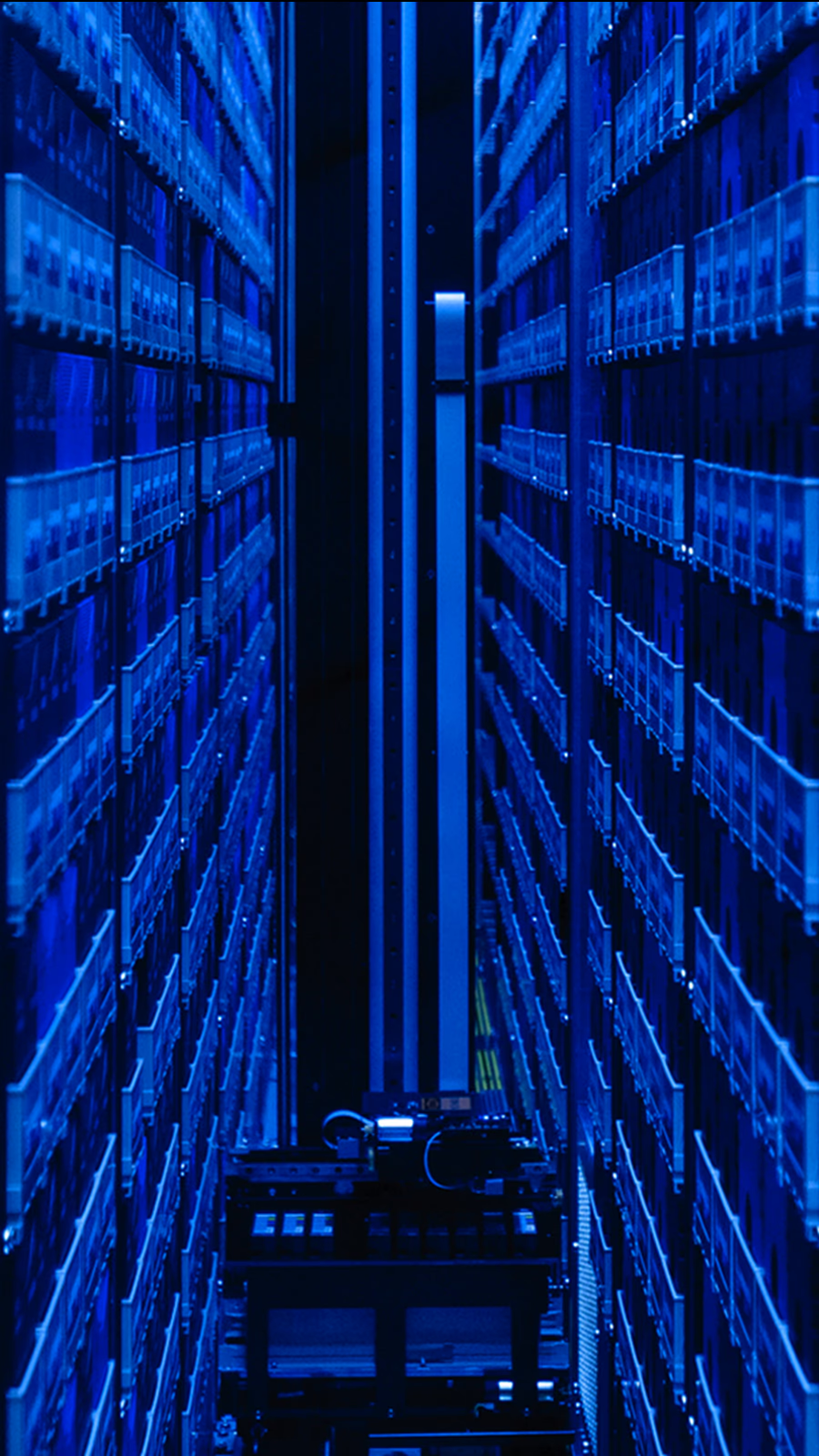
A blue-lit robotic tape archive aisle with cartridge racks rising on both sides.

A robotic tape library represents the coldest end of a multi-tier data lifecycle.

Archive capacity is not online bandwidth: retrieval latency, staging space, media policy, and recovery tests determine whether retained data is usable.NASA content is generally not subject to U.S. copyright. The image documents an archival tier; it does not imply tape serves online checkpoints, training reads, or inference traffic.NASA Advanced Supercomputing Division.Original sourceNASA media usage guidelines

Spread 10 / Checkpoint and restore

Protected progress

A checkpoint is an economic boundary

It defines how much completed computation can be lost.

Long-running training jobs periodically write model state, optimizer state, scheduler state, and enough metadata to restart consistently. The interval sets a tradeoff: frequent checkpoints consume storage and network resources, while infrequent checkpoints expose more expensive work to a fault. The correct cadence depends on job cost, failure rate, checkpoint duration, restore time, and whether the application can write asynchronously without distorting progress.

A checkpoint is useful only if it is complete, discoverable, and restorable. Operators need integrity checks, version compatibility, retention rules, and tests that actually restart jobs from saved state. Replication can protect against media loss but does not guarantee logical correctness. The recovery process should be measured as carefully as the write path because an impressive checkpoint rate can coexist with a slow or unreliable return to useful computation.

Recovery point
The amount of completed work exposed between recoverable states.
Recovery time
The interval from failure detection to resumed useful work.
Consistency
The requirement that saved components represent one valid application state.
Set checkpoint cadence from expected loss
  1. Measure— Record checkpoint size, freeze time, asynchronous tail, network and storage load, and verified restore duration.
  2. Model— Compare saved-work interval with job failure behavior, compute cost, retention, replication, and recovery objectives.
  3. Coordinate— Stagger large jobs or stage writes so synchronized protection does not starve datasets, logs, or neighboring services.
  4. Revisit— Update cadence when model state, topology, software, storage load, failure rate, or business value changes.

Burst engineering

Plan the write storm

Synchronized jobs can ask storage for protection at the same moment.

Checkpoint traffic is often bursty because workers reach the save boundary together. If several large jobs align, the storage backend and network can see a demand spike far above the daily average. Staggering, incremental methods, local staging, compression, and dedicated paths can smooth the event, but each technique shifts work into compute, memory, local capacity, or operational complexity.

The infrastructure team should treat checkpoint windows as scheduled failure tests. Observe queue growth, backpressure, job progress, and recovery copies; then inject a fault while the system is busy. The result reveals whether the design protects both the current job and its neighbors. Storage guidance for AI emphasizes the paired requirement: ingest must feed accelerators, and checkpoint and recovery must preserve their costly time.

Operational test: A checkpoint is not complete when bytes are acknowledged. It is complete when the organization can prove that a compatible job restarts from it.
A restore drill proves more than readable bytes
GateProof required
DiscoveryThe correct checkpoint is found through the production catalog after simulated loss
IntegrityAll components, manifests, checksums, encryption keys, and dependencies form one valid state
CompatibilityCurrent or approved rollback software can interpret and load the saved representation
PlacementReplacement compute, memory, network, and storage resources can be acquired without deadlock
ProgressThe job resumes useful work and matches an expected validation signal

Spread 11 / Memory as fabric

Coherent expansion

CXL extends the memory conversation

Pooling can improve access to capacity, but distance and sharing remain real.

Compute Express Link adds coherent protocols to a PCIe-based physical foundation so processors and devices can participate in richer memory relationships. The specification family includes use cases for attached memory, switching, sharing, and pooling. That creates architectural options when local memory capacity is scarce or stranded across hosts, and it can separate some memory lifecycle decisions from a single server configuration.

Pooling is not free local memory. A remote or shared tier has additional latency, bandwidth limits, switching behavior, security boundaries, and failure modes. Software must know which allocations tolerate those properties. Operators must observe contention and preserve isolation among tenants or jobs. The opportunity is to match more memory classes to actual access patterns—not to pretend that every byte is equally near to every processor.

One of the fabric-attached memory capabilities supported in CXL 3.1 materials.
Memory pooling
Evidence class
fact
Claim
claim-cxl-pooling
Context
Capability in a standard does not imply uniform latency, availability, or deployment across products.
Memory expansion changes semantics as well as capacity
Coherent access
Participating agents observe memory through an ordering and cache-consistency contract that adds protocol state and recovery requirements.
Expansion
One host reaches additional capacity beyond its local channels, accepting a distinct latency, bandwidth, topology, and failure profile.
Pooling
Capacity can be assigned among hosts, creating control-plane, isolation, revocation, accounting, and fragmentation responsibilities.
Tiering
Software places data among memory classes and must identify when migration cost or access distance erases the capacity benefit.

Placement

Tier memory by behavior, not hope

Application awareness decides whether expanded capacity is useful.

An allocator can place hot model state in the fastest local memory, warm or overflow state in an expanded coherent tier, and durable artifacts in storage. Making that hierarchy work requires profiling reuse, migration costs, and sensitivity to tail latency. A capacity gain that causes frequent remote access may slow the job more than a smaller local working set would.

The same discipline applies to failure. If shared memory disappears, the runtime needs a defined response: retry, reconstruct, checkpoint, or terminate. Firmware, operating systems, hypervisors, libraries, and applications must agree on discovery and errors. Fabric-attached memory therefore sits at the intersection of hardware standards, platform validation, scheduling, and application design. It is a new resource boundary, not merely another module installed in a rack.

A practical memory hierarchy
TierBest suited toDesign concern
Accelerator HBMHottest model stateScarce capacity
Host memoryCPU-visible working stateSocket locality
Fabric-attachedShareable or expandable stateDistance + contention
StorageDurable data and recoveryAccess latency
Pooling needs tenant and failure policy
  • Authorize allocation, mapping, migration, and revocation with workload identity; clearing and key rotation must complete before capacity is reassigned.
  • Define behavior when a device, link, switch, manager, or host fails while pages are dirty, cached, migrating, or shared.
  • Measure bandwidth and latency under competing tenants, not only one consumer, and expose noisy-neighbor limits to admission and chargeback.
  • Keep topology visible to software so remote capacity is not presented as interchangeable with on-package or local memory when performance objectives differ.

Spread 12 / Observe and recover

Operations

The fabric needs one timeline

Application stalls must be correlated across layers that report time differently.

A slow step may originate in an accelerator kernel, host queue, adapter, link, switch buffer, storage controller, metadata service, or distant worker. Each layer has its own counters and vocabulary. Without synchronized clocks, stable identifiers, and a shared event model, teams can spend an outage proving that their component is healthy while the composed system remains unusable.

Effective observability follows a job across the stack. It joins scheduler placement, collective timing, endpoint counters, route changes, optics health, storage latency, firmware events, and facility maintenance. Baselines distinguish normal bursts from degradation, and retention preserves evidence after a transient fault. The purpose is not to collect every metric; it is to shorten the path from lost useful work to a bounded cause and a safe recovery action.

Evidence for one stalled step
  • Job, rank, node, adapter, port, and route identity
  • Collective duration and application progress
  • Queue, retry, correction, and loss counters
  • Storage latency, topology changes, and maintenance events
Control plane from request to release
  1. Admit— Authenticate the workload, enforce quota and policy, and reserve the complete gang or service allocation before partial placement fragments supply.
  2. Place— Match accelerator type, memory, topology, storage locality, network class, software, and maintenance state to declared requirements.
  3. Operate— Observe progress and health, rescale or preempt under policy, and preserve checkpoint and tenant accounting boundaries.
  4. Release— Revoke credentials and direct access, clear tenant state, reconcile usage, and return only validated resources to the pool.

Documentary plate

Operations happen at the rack

Remote telemetry eventually meets physical inspection and replacement.

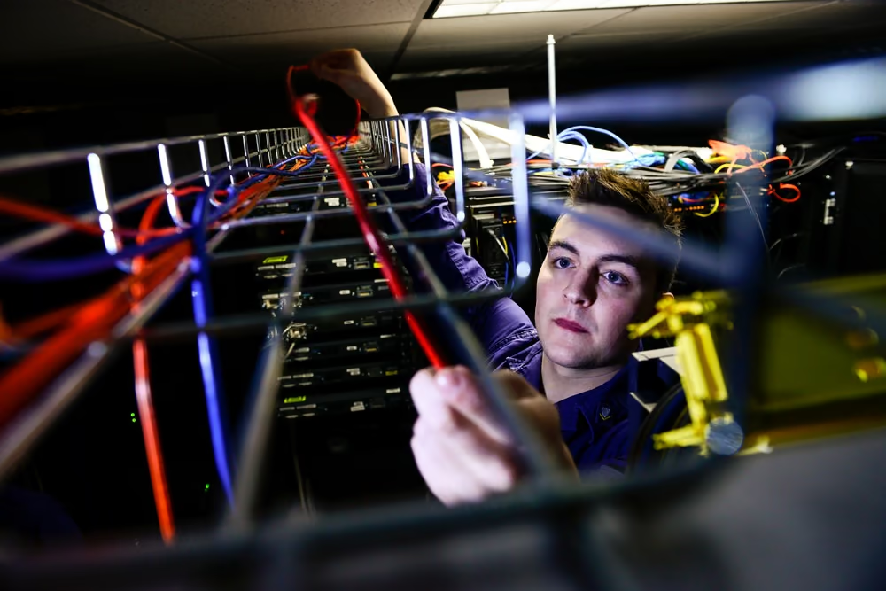
A management system may identify a failing port, but a technician still needs an accurate rack, cable, spare, procedure, and maintenance window. Serviceability determines how quickly degraded capacity returns. Dense installations complicate access because power, coolant, and communication paths occupy the same space; a repair must avoid disturbing healthy neighbors or creating a new shared failure.

This image shows personnel in a government server-room context, not a hyperscale AI training facility. It grounds a general operational truth: digital infrastructure has human touch points. Runbooks, labels, permissions, safety boundaries, and replacement practice are part of network availability. Designs that maximize port density while ignoring these activities can strand capacity during the very failures redundancy was intended to absorb.

A technician adjusting dense network cabling between equipment racks in a server room.

A server-room inspection provides context for the physical maintenance behind network availability.

Documentary context only; the pictured installation is not presented as an AI cluster.DVIDS marks the item public domain. It is documentary server-room infrastructure, not a current hyperscale AI deployment. The appearance of U.S. Department of War (DoW) visual information does not imply or constitute DoW endorsement. Individuals' publicity and privacy rights are not waived.U.S. Coast Guard photo by PO1 Luke Pinneo, via DVIDS, public domain.Original sourceU.S. government work / public domain
Tenancy controls differ by plane
PlaneRequired boundary
API and schedulerIdentity, authorization, quota, admission, audit, and change control
East-west networkDefault-deny policy, service identity, encryption where required, and egress control
RDMA and DMADevice assignment, memory-key lifecycle, isolation, revocation, and reset
Models and storageNamespace, encryption, provenance, retention, cache clearing, and access logs
ManagementSeparate privileged reachability, attestation, firmware trust, and break-glass recovery
PerformanceFair queues, bandwidth governance, topology admission, and noisy-neighbor evidence
04

The utilization layer

Compilers, runtimes, collectives, schedulers, and operating practice determine how much of the physical fabric becomes useful work.

Spread 13 / Programming stacks

Software stack

Hardware is reached through layers

The application depends on a chain of compilers, libraries, runtimes, drivers, and firmware.

Accelerator software stacks expose programming models, compile operations, dispatch kernels, manage memory, invoke communication libraries, and translate errors from hardware. CUDA and ROCm each span these roles through related tools and interfaces. Above them sit frameworks and model libraries; below them sit drivers, operating systems, device firmware, and the platform controls that provide power, cooling, and connectivity.

Version compatibility is therefore an infrastructure dependency. A framework update may require a compiler, runtime, driver, or firmware change; a network feature may depend on a particular adapter and collective-library combination. Stable deployment uses tested version matrices, reproducible images, staged rollout, and rollback. The objective is not to freeze software forever, but to change the stack without turning the entire cluster into one experiment.

Compiler
Transforms model operations or source code into executable work for a target.
Runtime
Manages execution, memory, streams, devices, and errors while a program runs.
Kernel library
Optimized implementations of recurring mathematical and communication operations.
A supported stack is a tested matrix
LayerPin and record
FirmwareDevice, switch, BMC, DPU, storage, security, and rollback compatibility
Kernel and driverHardware support, memory model, IOMMU, RDMA, telemetry, and error behavior
Runtime and librariesCollectives, kernels, compiler, communication plugins, and numerical validation
Framework and modelGraph behavior, sharding, precision, checkpoint format, adapters, and serving engine
OrchestratorResource discovery, admission, topology, health, upgrade, and tenancy policy

Portability

An API is not performance parity

Compatibility, correctness, and tuned efficiency are separate achievements.

A workload can compile on more than one platform yet use different kernels, communication paths, memory behavior, and debugging tools. Portability reduces dependence only when the organization can validate correctness, reproduce results, tune bottlenecks, and operate the alternative at scale. The effort includes code, build systems, observability, staff knowledge, and a supply of comparable hardware—not a single translation flag.

Procurement should distinguish open interfaces from mature implementations and portable source from portable performance. A sensible strategy identifies which layers are strategic, which can be abstracted, and where vendor-specific optimization earns its operational cost. Evidence comes from representative jobs and failure drills. Marketing feature lists cannot reveal whether a particular model, topology, and team can sustain useful throughput across a full software lifecycle.

Evidence label: CUDA and ROCm are documented as complete accelerator software stacks. That fact does not assert feature parity or equal performance for any workload.
Software supply is part of fabric security
  • Verify provenance, signatures, dependencies, build inputs, registries, and deployment policy for drivers, firmware, containers, operators, and plugins with privileged access.
  • Stage upgrades on representative topology and traffic, including rollback, mixed-version boundaries, checkpoint compatibility, and fault recovery before fleet rollout.
  • Limit device plugins, operators, and network or storage agents to the permissions they require; convenience-level host access can collapse tenant isolation.
  • Retain the exact stack with benchmark and incident evidence so a performance or reliability change can be attributed instead of debated from memory.

Spread 14 / Parallelism

Work partition

How the model becomes traffic

Parallelism strategy writes the network's job description.

Data parallelism replicates model work across different samples and then coordinates updates. Tensor parallelism divides operations within layers. Pipeline parallelism divides sequences of layers into stages. Fully sharded approaches distribute parameters, gradients, and optimizer state. PyTorch documents these as complementary strategies because large jobs often combine them across nested groups rather than selecting only one.

Each choice creates a different communication graph. Some exchange large gradients at step boundaries; others move activations frequently; pipeline stages can wait on imbalance; sharding can trade memory capacity for additional transfers. The job planner should map these groups onto physical neighborhoods so the most frequent or sensitive exchanges use the strongest links. Model architecture, memory limits, fabric topology, and scheduler placement must be tuned together.

Parallelism changes the dominant exchange
StrategyWhat is dividedFabric concern
DataTraining samplesGradient synchronization
TensorLayer operationsFrequent low-latency exchange
PipelineLayer stagesStage balance and activation flow
ShardedModel and optimizer stateMemory saved versus communication
Parallelism creates different traffic
Data parallel
Replicas process different samples and exchange gradients or updates, producing synchronized collective traffic across the replica group.
Tensor parallel
Individual operations are split across devices, creating frequent, latency-sensitive communication within layers or kernels.
Pipeline parallel
Model stages exchange activations and gradients while schedule bubbles and imbalance determine how much installed compute remains idle.
Expert parallel
Tokens are routed among expert owners, creating workload-dependent all-to-all traffic and sensitivity to skewed demand.

Collectives

Communication is an algorithm

The route used to combine data can matter as much as the link speed.

Collective libraries implement operations such as all-reduce, all-gather, reduce-scatter, and broadcast across groups of workers. An implementation chooses rings, trees, hierarchies, or other patterns based on message size and topology. It may combine local scale-up links with a scale-out fabric, attempting to keep dense traffic inside fast neighborhoods and cross racks only when necessary.

Performance depends on coordination. If one worker arrives late, peers can wait even when the network is empty. If placement ignores physical links, a logical group may cross unnecessary tiers. Profiling must join compute timelines with communication traces to distinguish network delay from straggling work. The best tuning changes over the life of a model and cluster, so the mapping should be observable and repeatable rather than buried in defaults.

Co-design rule: Place the parallel group on the physical graph, then measure the collective inside the full training step. Neither view is sufficient alone.
Choose parallel layout with the fabric in the loop
  1. Fit state— Account for parameters, activations, gradients, optimizer or KV state, buffers, and fault reserve on each device.
  2. Map traffic— Describe message sizes, partners, frequency, ordering, overlap, synchronization, and burst alignment for every parallel dimension.
  3. Place groups— Keep the most latency-sensitive communication on the strongest physical domain while respecting failure and service boundaries.
  4. Measure progress— Compare full-step or request performance, tails, failures, energy, and recovery rather than optimizing one collective in isolation.

Spread 15 / Useful work

Scheduling

Utilization is an orchestration outcome

A busy device is not necessarily advancing the highest-value work.

Schedulers match jobs to accelerators, memory, local storage, network neighborhoods, software versions, and maintenance state. A placement that satisfies only device count can scatter a tightly coupled job across weak paths or leave fragments that future jobs cannot use. Queue policy also shapes economics: short inference services, interactive research, and long training runs have different preemption, latency, and checkpoint needs.

Useful utilization measures completed work against the resources and time consumed, including waiting, retries, failed jobs, and reserved capacity. Teams should separate allocation, device activity, application progress, and business output. This makes optimization honest: higher reported occupancy is not an improvement if jobs take longer, recovery becomes fragile, or operators lose the headroom needed to contain failures.

Four utilization layers
  1. Allocated: the scheduler assigned the resource
  2. Active: hardware counters show work
  3. Productive: the application advances correctly
  4. Valuable: the completed work serves the intended objective
Useful utilization has four different denominators
LayerMeasureFailure mode
AllocatedResources reserved by schedulerFragmentation or idle reservation
ActiveHardware executing or moving dataBusy retries, spin, or low-value work
ProductiveCorrect application progressStalls, replay, failed jobs, or latency misses
ValuableCompleted business or research objectiveOptimizing throughput that users do not need

Handoff

The fabric ends in operations, not at the port

Capacity survives only through maintenance, governance, and continuous evidence.

A production fabric needs ownership across networking, storage, platform software, machine learning, facilities, security, and finance. Change control must understand that a firmware update, cable replacement, route policy, library release, or maintenance window can alter model throughput. Capacity plans should include spares, growth blocks, failure reserve, and the labor to qualify changes—not only installed ports and bytes.

The final handoff is an evidence loop. Workload traces inform topology; topology informs placement; telemetry identifies loss; recovery tests validate protection; and measured progress updates the next procurement. This loop turns a collection of components into infrastructure. It also connects Fabric to Plant: every extra switch, optic, drive, and stalled watt becomes heat, power demand, construction space, and operational responsibility at the facility scale.

Close the loop
  1. Measure— Observe application progress and the resources consumed to produce it.
  2. Attribute— Locate delay or failure across software and physical paths.
  3. Change— Tune, repair, or expand through a controlled release.
  4. Verify— Replay representative work and update capacity assumptions.
Serving efficiency needs an SLO and a tenant denominator: Tokens per second is incomplete without the request distribution, time-to-first-token and inter-token targets, completion and error rates, model quality, cache policy, and wall energy. Report admitted, queued, rejected, canceled, and retried requests so overload is not hidden. Attribute accelerator time, memory residency, KV transfers, network, storage, and reserved headroom to the tenant or service; otherwise one workload can appear efficient while exporting delay and cost to its neighbors.

Behind the claim

Evidence, in context.

Opening the evidence record…