Intelligence BuildoutMethodology

Plant — complete text edition

Volume VI / Text edition

Plant

Sites + power + cooling. 15 spreads and 30 pages, with the complete evidence-linked content. No JavaScript is required.

Volume VI

Plant

Sites + power + cooling · 30 pages

How land, construction, electricity, water, heat rejection, and operations make a rack physically usable.

01

Choose the ground

A viable site aligns power, fiber, hazards, water, logistics, workforce, permits, and community context.

Spread 01 / Site as system

Orientation

The cloud lands somewhere

Every AI deployment becomes a site-specific industrial project.

A data-center campus joins a global technology supply chain to one parcel of land. At that boundary, abstract compute demand meets local transmission, distribution equipment, fiber routes, geology, weather, roads, water systems, construction labor, emergency services, zoning, taxation, and neighbors. No component can be evaluated independently because the cheapest land may have the longest grid schedule, while a power-rich site may lack fiber diversity or an acceptable cooling path.

Site selection is therefore systems engineering under uncertainty. Teams must identify hard constraints, model enabling work, assign schedule and cost risk, and distinguish capacity that is merely discussed from capacity that can be permitted, built, commissioned, and energized. A campus becomes useful only when all critical paths arrive together. Early diligence exists to expose the dependency that would otherwise appear after capital and schedule are committed.

The first site screen
  1. Reach— Confirm credible power and physically diverse fiber paths.
  2. Fit— Test geometry, hazards, water, roads, and adjacent uses.
  3. Permit— Map every jurisdiction, approval, study, and public process.
  4. Deliver— Sequence land, equipment, labor, construction, and commissioning.
Define the campus boundary before comparing sites
LayerEvidence the site case must include
ParcelBuildable area, easements, hazards, access, drainage, and expansion reserve
UtilityService point, upstream upgrades, fuel and water dependencies, and delivery status
FacilityIT, cooling, electrical, life-safety, security, and maintenance space
RegionalWorkforce, housing, emergency response, shared infrastructure, and community burden
LifecycleConstruction, operation, refresh, restoration, and decommissioning obligations
A site is a bundle of coupled constraints, not a dot on a map.

Threshold criteria

Cheap land can be expensive capacity

Parcel price is small beside missing infrastructure and delayed energization.

Developers compare land control, utility studies, substation and transmission work, fiber construction, grading, drainage, foundations, environmental controls, water and sewer arrangements, and access improvements. Each can require third-party action outside the developer's direct schedule. Tax incentives may improve project economics, but they do not repair unsuitable soils or create firm electrical capacity on demand.

EPA's redevelopment guidance illustrates the breadth of a responsible screen: candidate sites should fit their physical condition, reach power and fiber, comply with regulation and cleanup controls, and include planning and community input. The guidance addresses redevelopment contexts rather than every data-center project, yet its framing is useful. Suitability is not a single score. It is an evidence trail showing how the site can host the proposed facility without hiding unresolved obligations.

Decision gate: Do not convert a utility conversation, preliminary parcel, or conceptual design into an energized-capacity claim. Each milestone needs its own status and evidence.

A comparable site model uses the same demand case, reliability target, climate period, and project state for every candidate. Record who controls each enabling asset, what evidence supports availability, when it must arrive, and which dependency sits outside the developer's authority. Then test common-mode failures: one corridor may carry grid power, fuel, fiber, and water access despite separate contracts. The audit should end with residual risks, priced mitigations, decision owners, and a dated trigger for reopening the site choice.

Spread 02 / Land and hazards

Ground truth

Geometry and geology set the first limits

The buildable site is smaller than the parcel boundary.

Setbacks, easements, wetlands, drainage corridors, flood zones, slopes, protected resources, utility rights-of-way, and road access remove or condition areas that appear available on a map. Geotechnical investigation determines whether foundations, yards, tanks, and heavy equipment need soil improvement or special design. Campus planning must also reserve future blocks, construction staging, security buffers, stormwater controls, and safe maintenance access.

Hazard analysis extends across flood, wildfire, seismic activity, wind, heat, cold, smoke, dust, and adjacent industrial risk. The response is not to claim that every hazard can be eliminated. It is to define the exposure, design protections, operational thresholds, recovery plan, and residual risk. Climate assumptions should cover the expected facility life and equipment ranges rather than rely only on historical annual averages.

Land that must remain visible in the plan
  • Data halls, utility yards, substations, and heat rejection
  • Stormwater, setbacks, easements, and environmental controls
  • Construction staging, heavy-haul routes, and worker access
  • Future phases, maintenance clearances, and emergency response
Hazard analysis needs four separate terms
Exposure
The people, equipment, utilities, routes, and ecosystems that can encounter the hazard.
Vulnerability
How the proposed design and operating state respond when the hazard occurs.
Mitigation
A designed, operated, and maintained control with a named performance objective.
Residual risk
The consequence and uncertainty that remain after credited controls are applied.
Recovery
The resources, access, sequence, and time needed to restore safe service.

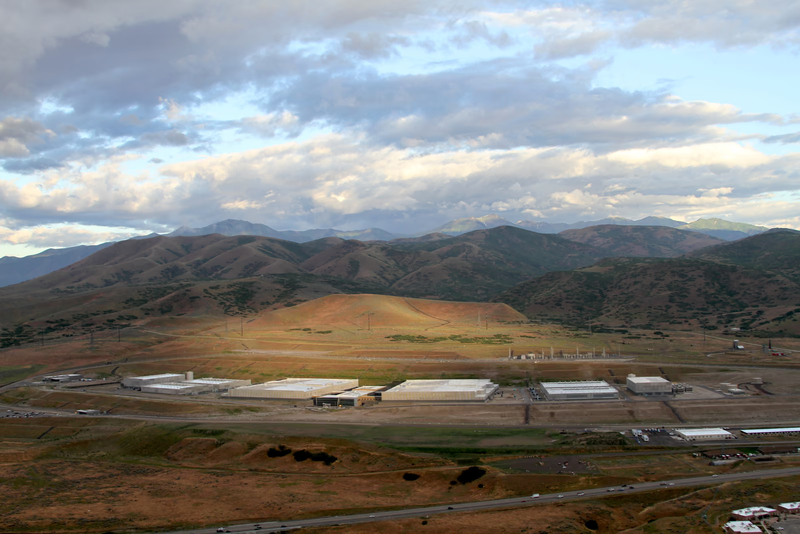
Documentary plate

A campus is more than a building

Support yards, security, access, and utility space define the operating footprint.

This aerial image depicts a government data-center campus. It is not an OpenAI project, a hyperscale AI training campus, or evidence of the density and equipment described elsewhere in this volume. It is used to reveal site relationships that close photographs hide: buildings sit within roads, perimeter space, mechanical areas, drainage, utility access, and a larger land context.

An AI facility may arrange those elements differently and can demand much greater power or cooling infrastructure. The planning lesson still holds. Site capacity must include everything required to operate and expand safely, not only the white-space floor area. A credible master plan marks the boundaries between current work, reserved expansion, third-party infrastructure, and land that cannot be developed.

Aerial view of a large data-center campus with several long halls, support buildings, roads, and electrical infrastructure.

A government data-center campus viewed from above, showing buildings within a broader operating site.

Documentary context only. This is not a hyperscale AI campus and should not be read as a project-performance example.The creator released the photograph under CC0. It depicts a U.S. government data center, not an AI hyperscale campus or the Stargate project.Parker Higgins / Electronic Frontier Foundation, CC0.Original sourceCC0 1.0 Universal
Questions an all-hazards site file should answer
  • Which historical, forward climate, geological, and adjacent-facility evidence defines the design basis?
  • Do protected routes and redundant systems share a floodplain, fuel source, control room, bridge, or maintenance crew?
  • Can emergency responders reach and isolate the site during the same event that interrupts utilities?
  • Which protective systems require inspection, vegetation control, drainage maintenance, testing, or operator action?
  • What conditions stop work, shed load, shelter staff, trigger evacuation, or require public notification?

Spread 03 / Reach the site

Connectivity

Fiber diversity must be physically true

Multiple contracts can still share one vulnerable trench.

A campus needs high-capacity routes to users, other data centers, cloud regions, and carrier networks. Teams inspect long-haul reach, carrier availability, entrance diversity, conduit ownership, splice locations, rights-of-way, and the route inside the property. Logical diversity from two providers is weak if both lease the same buried segment or enter through one room. Construction and repair times for new fiber belong in the project schedule.

The campus network also has lifecycle needs. Additional halls consume strands and pathway space; optical generations change equipment; maintenance requires access without exposing both routes; and a civil project outside the fence can threaten multiple services. Route records should identify shared-risk groups from carrier points of presence to internal distribution. Connectivity is not fully delivered until paths are built, tested, documented, and accepted under failure.

Diversity test: Ask for maps, conduit ownership, entrance details, and shared-risk groups. Provider names alone do not prove independent physical paths.
Prove physical network diversity
  1. Trace— Map each path from carrier facility through conduit, entrance, meet-me room, and internal distribution.
  2. Disclose— Identify shared owners, bridges, poles, ducts, power supplies, splices, and restoration crews.
  3. Test— Fail one path under representative traffic and observe routing, congestion, alarms, and recovery.
  4. Protect— Control excavation, access, change work, spares, and documentation across the full route.
  5. Recheck— Repeat the shared-risk review when carriers, construction phases, or upstream routes change.

Logistics + labor

The critical path arrives by road and by hand

Long-lead equipment is useless without transport, staging, and qualified installation.

Transformers, switchgear, generators, cooling equipment, steel, electrical rooms, modular assemblies, and racks can demand special transport and lifting plans. Bridge limits, road geometry, delivery windows, laydown space, weather, and security affect when equipment can reach its foundation. Phased campuses need routes that allow later construction without compromising live operations or emergency access.

Labor is another infrastructure layer. Civil, structural, electrical, mechanical, controls, fiber, safety, commissioning, and operations skills peak at different times. Local availability, training, travel, housing, and competing projects can constrain the sequence. A schedule that assumes every trade appears exactly when needed is not a schedule; it is an unpriced dependency. Workforce planning should begin with design and continue through permanent operations.

Delivery has two linked chains
Equipment chainWorkforce chain
Factory slotQualified design
Transport + stagingTrade availability
InstallationSafety + supervision
AcceptanceCommissioning + operations handoff
A delivery plan joins freight, craft, and live-site controls
GateAudit evidence
Factory releaseAccepted test record, configuration, preservation, and ownership at handoff
Heavy transportRoute survey, permits, weather limits, escorts, lifting points, and contingency
InstallationQualified craft, supervision, energized-work boundary, tooling, and inspection hold points
TurnoverAs-built records, training, spares, warranty, safe access, and unresolved-item owner
Later phasesSegregated routes so expansion work does not disable operating halls or emergency response

Spread 04 / Permission to break ground

Jurisdiction

There is no single data-center permit

The required path depends on site, design, infrastructure, and public authority.

In the United States, data-center siting is commonly governed through state and local land-use authority, building and fire codes, and utility processes. Federal involvement varies. Wetlands or waterways, federal land or funding, air emissions, water discharges, transmission, pipelines, or a nuclear project can create different federal nexuses. CRS emphasizes that the actual mix is project- and location-specific.

A permit matrix should name the agency, legal trigger, application, studies, dependencies, public process, decision standard, appeal risk, conditions, and renewal obligation. It should also distinguish a filed application from an approval and an approval from a condition that has been satisfied. Construction sequencing must respect these gates; starting enabling work before authority is clear can strand capital or damage community trust.

Federal nexus
A project feature that brings a federal approval, resource, law, or agency into the review path.
Land-use approval
Local or state authorization governing whether and how the use fits the site.
Permit condition
An enforceable requirement attached to an approval and carried into design or operation.
Minimum fields in a decision-grade permit register
FieldWhy it matters
Legal triggerExplains why the approval applies and which project boundary it governs
Decision authorityNames the agency, utility, reviewer, appeal path, and responsible project owner
Evidence stateSeparates planned, submitted, complete, approved, conditioned, and closed milestones
DependenciesConnects studies, hearings, designs, construction packages, and third-party actions
Operating dutyCarries limits, monitoring, reporting, renewal, financial assurance, and enforcement forward

Project states

Phases prevent paper capacity from becoming fact

A campus can exist in several different senses long before it operates.

Announcements describe intent. Land control provides a site interest. Permits authorize defined work. Utility approval establishes a path subject to conditions. Construction creates assets. Energization delivers electrical capability. Operations demonstrate that the commissioned system can host workload. These states are related but not interchangeable, and a multi-building campus may occupy several at once.

Phasing can reduce risk by aligning each block with committed power, cooling, network, and customers. It can also create stranded interfaces when later blocks change density or never arrive. The master plan must identify which shared assets are built up front, who funds them, and how early phases operate independently. Public communication should state the unit—land, shell, IT megawatts, facility load, or energized capacity—and the date of its evidence.

Abilene illustrates the distinction. Crusoe reported Stargate's first phase live and its first two buildings energized in September 2025; OpenAI later described the site as operating on Oracle Cloud Infrastructure with NVIDIA GB200 systems in April 2026. Those dated operator and developer statements support an operating-state label for part of the campus. They do not turn planned later buildings, performance claims, or full-buildout capacity into measured fact.Claim

Capacity maturity
  1. Control— Secure an evidenced interest in a suitable site.
  2. Authorize— Obtain the approvals and utility conditions for defined work.
  3. Build— Install and accept the civil, electrical, mechanical, and network systems.
  4. Energize— Demonstrate commissioned capacity under operating conditions.

Phase labels should describe independently operable systems, not marketing increments. For each phase, reconcile land authority, approved design, utility service, emergency access, cooling and water capacity, network paths, staffing, commissioning, and the customer or workload gate. Shared assets need an allocation rule if later construction is delayed or cancelled. Public reporting should retain both the unit and status date—building shell, connected load, commissioned facility load, or usable IT capacity—so an early permit or energization milestone cannot silently become full-campus operating capacity.

02

Build the envelope

Sequence civil works, halls, power distribution, resilience, controls, and commissioning around long-lead dependencies.

Spread 05 / Critical path

Construction

The schedule is a dependency graph

Steel and concrete are visible; studies, factory slots, and controls often decide the date.

A campus schedule connects design packages, permits, site preparation, foundations, structural work, utility infrastructure, electrical and mechanical equipment, network rooms, controls, racks, and testing. Long-lead items may need orders before every downstream detail is final, creating interface risk. Off-site manufacturing and modular assembly can compress field work, but only when dimensions, utilities, firmware, transport, and acceptance criteria are controlled.

The critical path should be modeled as evidence, not ceremony. Each activity needs an owner, prerequisite, promised date, confidence, and recovery option. Shared infrastructure deserves special attention: a delayed substation or cooling plant can hold multiple completed halls. Conversely, phased designs can release useful capacity early if each block has independent protection, controls, and safe access while neighboring construction continues.

Frequently hidden schedule gates
  • Utility studies, transmission work, and protection settings
  • Factory acceptance and transport of long-lead equipment
  • Controls integration across multiple vendors
  • Commissioning labor, test loads, and issue closure
Build a critical path that can be audited
  1. State— Define the commissioned capacity and reliability outcome the milestone must deliver.
  2. Network— Link permits, designs, factory slots, civil work, utility outages, controls, and testing.
  3. Resource— Attach accountable teams, qualified labor, access, equipment, spares, and decision dates.
  4. Stress— Model late approvals, failed tests, rework, weather, transport, and shared-resource conflicts.
  5. Rebaseline— Preserve the prior plan, explain variance, and distinguish recovery action from optimism.

Capital sequence

Spend follows uncertainty down the chain

Construction converts reversible options into fixed interfaces.

Early site and design work preserves choices; equipment deposits, foundations, and utility upgrades progressively lock the project into a location and architecture. Global data-center investment has reached a scale that makes these sequencing decisions economically significant. Yet an industry total does not validate any single campus. Each project still needs demand evidence, phase-specific financing, contingency, and a credible path to energized use.

Change control is essential because compute density can evolve faster than construction. A later rack design may require different floor loading, busway, coolant temperatures, pipe sizes, or network pathways. Flexible interfaces can absorb bounded change, but unbounded future-proofing wastes capital. Teams should state the design envelope, price options at phase gates, and record which assumptions would force redesign.

IEA estimate of global data-center investment in 2024, rounded to roughly half a trillion U.S. dollars.
~$500B
Evidence class
estimate
Claim
claim-dc-investment-2024
Context
The aggregate is context for industry scale, not evidence of a particular project's value or readiness.
Schedule claims that deserve challenge
  • A purchase order is not a protected factory slot unless configuration, release conditions, and delivery terms are settled.
  • Equipment on site is not installed capacity until interfaces, protection, controls, and documentation are accepted.
  • Mechanical completion is not readiness: functional and integrated testing may expose system-level rework.
  • Float shared across phases, trades, or utility outages can be consumed only once and needs a named owner.
  • Recovery plans should show added resources, changed logic, safety effects, and the new confidence range—not only a new date.

Spread 06 / The data hall

Building system

The hall is a serviceable machine room

Structure, power, coolant, network, controls, and people share one volume.

A data hall must carry rack weight, preserve equipment clearances, route power and network paths, distribute and return coolant, control leaks, manage fire risk, and allow safe replacement. Floor grids, ceiling heights, loading docks, corridors, and overhead structure are not background architecture; they constrain how quickly dense equipment can be installed and repaired.

Modern AI racks may arrive as integrated systems with prescribed power, cooling, and network interfaces. The hall should standardize those boundaries while containing failures. Leak zones, branch isolation, electrical protection, fire detection, access control, and monitoring need coordinated layouts. Mock-ups can reveal conflicts before repetition multiplies them across rows. The goal is a repeatable cell that remains understandable during an alarm, not only a visually ordered room on opening day.

Five layers in one hall
LayerDesign question
StructureCan it carry and move the equipment safely?
ElectricalCan faults be isolated without broad interruption?
CoolingCan heat be removed in normal and degraded states?
NetworkCan paths grow and be repaired without disturbance?
OperationsCan people identify, reach, and replace the failed unit?
Load measures inside the hall
Nameplate
Manufacturer rating; useful for protection and compatibility, not a forecast of coincident use.
Connected load
The installed equipment that could draw power within the defined boundary.
Demand
Observed or modeled power over a stated interval, workload mix, and operating condition.
Capacity
Power and heat-removal capability available after redundancy, derating, and operating limits.
Headroom
The remaining verified margin before a stated electrical, thermal, structural, or control limit.

Density transition

Rack power redraws the room

Higher density changes the interfaces upstream and downstream of compute.

NVIDIA's DGX GB200 documentation describes one rack-scale platform around an approximately 120-kilowatt envelope. Open Compute Project workstreams discuss future AI rack envelopes from 250 kilowatts toward one megawatt alongside liquid-cooling standards. These are a current product specification and a forward-looking roadmap, respectively—not evidence that every installed rack operates at those levels.

They nevertheless expose the direction of design pressure. Cabling, busways, protection, coolant distribution, floor loading, heat rejection, controls, and technician safety all change as more power concentrates in one service zone. A hall designed around much lower densities cannot be upgraded by replacing servers alone. Facility envelopes should declare the supported rack mix, diversity assumptions, coolant conditions, and degraded-mode limits.

Approximate rack power envelope documented for NVIDIA's DGX GB200 system.
~120 kW
Evidence class
vendor_spec
Claim
claim-gb200-rack-power
Context
Actual facility demand depends on installed configuration, workload, utilization, and supporting infrastructure.
High density changes access as well as cooling
BoundaryEvidence before release
Rack and floorStatic and dynamic load, anchorage, vibration, handling route, and lifting method
ElectricalFault duty, selective protection, grounding, cable heat, arc-flash controls, and isolation
ThermalInlet limits, flow balance, containment, coolant interface, alarms, and degraded mode
Life safetyDetection, suppression, egress, smoke control, responder access, and shutdown logic
OperationsSafe service clearances, tools, spares, staffing, procedures, and configuration ownership

Spread 07 / Voltage path

Electrical chain

Trace voltage from grid to package

Every conversion adds equipment, loss, protection, and a failure boundary.

Power may enter through transmission or distribution service, pass through a campus substation, medium-voltage switchgear, transformers, distribution gear, UPS systems or other ride-through devices, busways, rack power shelves, and board-level converters before reaching silicon. The exact architecture varies, but every stage must be rated, coordinated, monitored, maintained, and cooled.

Protection engineering decides which breaker or relay acts during a fault so the smallest safe portion is isolated. Redundancy decides which path carries load during maintenance or failure. Efficiency determines how much purchased energy becomes IT work rather than heat. Power-quality studies address voltage, harmonics, grounding, and fast load behavior. The facility and compute teams must share these assumptions because platform changes alter the electrical system's operating profile.

One-way energy, two-way evidence
  1. Receive— Utility service enters through studied and protected interconnection equipment.
  2. Transform— Voltage is stepped and distributed across campus and hall layers.
  3. Convert— Rack and board systems produce the rails consumed by electronics.
  4. Measure— Meters reconcile losses, load shape, quality, and available headroom.

Trace electrical capacity from the utility delivery point to the computing load with voltage, fault duty, protection, conversion loss, redundancy state, and environmental derating at every interface. A headline service rating can exceed the amount usable by racks after auxiliaries and reserved redundancy, while a downstream bottleneck can strand upstream equipment. The model should represent normal, maintenance, and contingency configurations; identify which components are concurrently maintainable; and show whether controls, batteries, fuel, cooling, or operator response become the limiting dependency during each transition.

Documentary plate

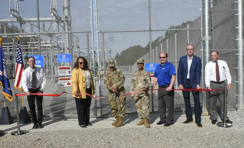
The substation is part of compute

A rack cannot use capacity that the site cannot receive, transform, and protect.

Substations contain transformers, breakers, bus, instrument transformers, protection, controls, and communication systems that connect a large load to the wider network. Their design and construction can sit on the campus critical path, while their failure modes can span many halls. Utility ownership boundaries determine who specifies, operates, and repairs each element.

The image shows a military-installation substation, not equipment serving a hyperscale AI campus. It is included as documentary context for the industrial footprint behind digital load. An AI project may use different voltage levels, ownership, redundancy, and layout, but it still depends on heavy electrical infrastructure, trained operators, spare strategy, clearances, and coordinated protection before any server can energize.

Military personnel and civilian officials hold a red ribbon in front of fenced electrical-substation equipment at a commissioning event.

A ribbon-cutting in front of a newly completed electrical substation documents the institutional as well as physical work behind power delivery.

The fenced equipment is partly obscured by event participants; the pictured substation is not identified as serving an AI data center.DVIDS marks the item public domain. The ribbon-cutting documents a completed substation; the facility is not identified as serving a data center. The appearance of U.S. Department of War (DoW) visual information does not imply or constitute DoW endorsement. Individuals' publicity and privacy rights are not waived.Photo by Terrance Bell / U.S. Army Fort Lee, via DVIDS, public domain.Original sourceU.S. government work / public domain
Control electrical work across the lifecycle
  1. Identify— Maintain an accurate one-line, equipment identity, sources, stored energy, and operating state.
  2. Plan— Define shutdown, transfer, isolation, grounding, arc-flash, access, and workload consequences.
  3. Verify— Prove absence or control of hazardous energy using approved methods and test equipment.
  4. Execute— Use qualified personnel, hold points, communications, and protection from adjacent systems.
  5. Restore— Inspect, remove controls deliberately, test interlocks, update records, and monitor re-energization.
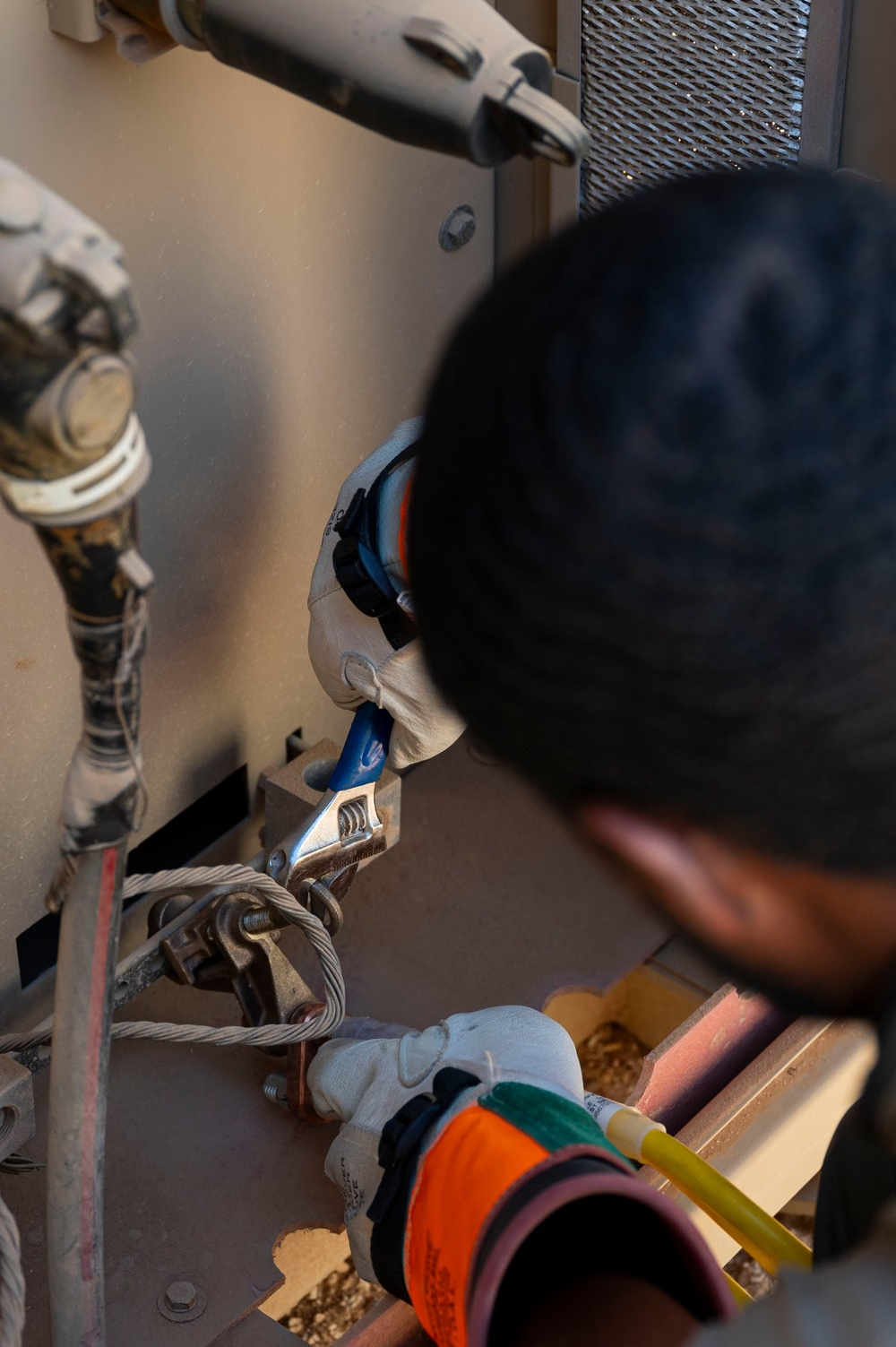
An electrician wearing protective equipment tightens a connection inside electrical distribution equipment.

Electrical capacity remains an operated and maintained system after commissioning.

The photograph documents maintenance practice outside a commercial data center; it is used for the human and safety layer, not as a reference power-train design.DVIDS marks the item public domain. The image documents secondary electrical-distribution work and safety practice, not a commercial data-center power train. The appearance of U.S. Department of War (DoW) visual information does not imply or constitute DoW endorsement. Individuals' publicity and privacy rights are not waived.U.S. Air Force photo by Senior Airman David Lynn, via DVIDS, public domain.Original sourceU.S. government work / public domain

Spread 08 / Prove the plant

Resilience

Backup is a timed sequence

Availability comes from coordinated transitions, not a row of redundant assets.

When utility service degrades, protection, ride-through, batteries, generators or other backup sources, controls, and load policies must respond in a defined order. Some systems bridge only seconds; others support longer operation. Fuel supply, emissions limits, maintenance state, ambient conditions, starting reliability, and concurrent failures all bound the duration that nameplate backup can provide.

Resilience design starts with service objectives and failure scenarios. It identifies which loads remain, which can be shed, how cooling continues, and when software should checkpoint, migrate, or shut down. Shared dependencies—controls networks, fuel systems, cooling pumps, switchgear rooms—must be included. A duplicate server path is irrelevant if both sides depend on one untested control or heat-rejection system.

Failure rule: Define the load that survives, the duration it survives, the transition sequence, and the degraded cooling state. The word redundancy alone answers none of these.
Commission the operating claim, not isolated equipment
  1. Specify— Turn the reliability narrative into testable sequences, limits, alarms, and acceptance criteria.
  2. Inspect— Verify installation, labeling, protection, calibration, software versions, and maintainable access.
  3. Function— Test each system through normal, degraded, transfer, trip, restart, and manual modes.
  4. Integrate— Exercise coupled power, cooling, controls, network, life-safety, and staffing scenarios.
  5. Sustain— Close deficiencies, train operators, baseline trends, and schedule periodic recommissioning.

Commissioning

Completion is demonstrated behavior

Installed equipment becomes capacity only after integrated testing and issue closure.

Commissioning verifies documents, installation, controls, setpoints, alarms, sequences, performance, and maintainability from individual components through the integrated facility. Functional tests challenge normal and failure modes: utility loss, equipment isolation, transfer, cooling interruption, sensor failure, network loss, and restoration. Temporary load banks or staged IT loads help prove behavior before valuable compute carries the risk.

Results need traceability. Deficiencies are assigned, corrected, retested, and incorporated into as-built records and operating procedures. Operators participate before handoff so they understand the plant's real behavior, not only its design narrative. A hall is energized when power is present; it is operational when the organization can safely run, observe, maintain, and recover it within stated limits.

Evidence of readiness
  1. Inspect— Verify installation and records against the approved design.
  2. Function— Exercise every component and control sequence.
  3. Integrate— Test interacting systems under normal and failed conditions.
  4. Handoff— Close issues, train operators, and preserve verified baselines.
OT assurance belongs inside resilience
  • Inventory controllers, sensors, actuators, gateways, remote access, firmware, owners, and physical locations.
  • Segment by consequence and required communication while preserving deterministic control and safety functions.
  • Test fail-safe behavior when telemetry, time, network, credentials, or a supervisory service is unavailable.
  • Require authenticated, recorded vendor access with an approved window, rollback plan, and local operator awareness.
  • Exercise recovery from trusted configurations and retain manual procedures that operators can safely perform under pressure.
03

Move the heat

Heat travels through a chain from silicon to the atmosphere; every interface sets a density and reliability limit.

Spread 09 / Heat path

Thermodynamics

Nearly every watt becomes heat

Cooling is the reverse supply chain of electrical power.

Electrical work entering processors, memory, networks, storage, and power electronics ultimately appears as heat that must leave the equipment. The path runs from semiconductor junctions through package materials and thermal interfaces to a heat sink or cold plate, then through air or liquid distribution, facility loops, and heat-rejection equipment into the environment. The weakest interface limits safe operation.

Density makes boundaries visible. A facility can have enough total cooling capacity yet fail at one cold plate, hose, manifold, row, pump, or exchanger. Designers therefore specify temperatures, flow, pressure, water quality, allowable approach, redundancy, and control response at every handoff. Compute telemetry and facility telemetry must share a timeline so throttling, hotspots, pump changes, and ambient conditions can be attributed correctly.

Follow one watt outward
  1. Junction— Silicon generates heat during computation and data movement.
  2. Capture— Package interfaces and cold plates or air sinks collect it.
  3. Transport— Air and liquid loops carry heat away from the rack.
  4. Reject— The facility transfers heat to ambient air, sometimes using water.
Do not collapse the heat path into one temperature
Heat load
Thermal energy that must cross the defined interface under a stated workload.
Approach
Temperature difference that enables heat transfer across an exchanger or rejection stage.
Flow
Mass or volume movement whose usefulness also depends on fluid properties and distribution.
Pressure margin
Available differential after piping, fittings, valves, filters, and elevation losses.
Thermal resistance
Temperature rise per unit heat flow across a defined material or interface.

Thermal envelope

Rated power is not a cooling profile

Location, timing, and workload variation shape the heat the plant must remove.

A rack power specification bounds design, but actual heat varies with configuration, utilization, power caps, workload phase, and efficiency. Transient changes can be rapid at the electronics while fluid and building systems respond more slowly. Controls must keep temperatures inside safe limits without hunting, starving neighboring branches, or turning every short burst into an unnecessary plant response.

Thermal qualification combines steady state, transients, partial load, maximum ambient conditions, and component failures. It confirms not only that equipment avoids shutdown, but that performance remains predictable. A design that depends on continuous throttling has converted missing cooling into hidden lost compute. A design with excessive headroom may waste capital and pumping or fan energy. The operating envelope should make this tradeoff explicit.

Future AI rack envelopes discussed in Open Compute Project roadmap workstreams.
250 kW → 1 MW
Evidence class
projection
Claim
claim-ocp-rack-envelope
Context
A standards-community roadmap is not a statement that these rack densities are broadly deployed today.
Instrument every transfer boundary
BoundaryTrend together
Die to packageWorkload, component temperatures, throttling, and error behavior
Package to cold plateContact condition, supply temperature, flow, pressure, and leak state
Technology loopRack branch balance, chemistry, filter condition, pump state, and return temperature
Facility loopExchanger approach, plant flow, storage, control command, and auxiliary power
Ambient rejectionWeather state, fan or pump output, plume or water condition, and delivered capacity

Spread 10 / Air and liquid

Cooling architecture

Air remains useful until flux and density outrun it

The relevant boundary is where heat is captured, not a slogan about liquid.

Air cooling moves conditioned air through equipment, captures heat in the exhaust, and returns it to cooling equipment. Containment prevents hot and cold streams from mixing, while fans overcome equipment and room resistance. Air is familiar and serviceable, but fan power, acoustic load, airflow volume, and local hotspot control become more challenging as heat concentrates.

Direct-to-chip liquid cooling places cold plates on the hottest components and carries much of their heat through liquid loops. Other components may still depend on air, making many deployments hybrid. Immersion places equipment in a dielectric fluid and changes component, service, material, and safety assumptions. The correct choice follows heat flux, rack density, climate, water strategy, maintainability, supply support, and the actual platform warranty envelope.

Cooling boundaries
ModeHeat captureKey design burden
AirEquipment airflowVolume, mixing, fan energy
Direct liquidCold plates on target devicesFluid interfaces and residual air load
ImmersionEquipment in dielectric fluidService model and material compatibility
HybridMultiple pathsCoordinated controls and accounting
Cooling modes move constraints rather than erase them
ModePrimary audit boundary
Room airAirflow path, recirculation, filtration, fan energy, and inlet distribution
Rear-door exchangeRack airflow plus door water, hose access, condensation control, and weight
Direct-to-chipCold-plate contact, coolant distribution, leak control, chemistry, and residual air load
ImmersionFluid compatibility, service procedure, fire strategy, lifting, filtration, and material recovery
Hybrid hallControl authority and failure behavior where multiple modes share space and rejection

Design choice

Liquid moves the interface into the rack

That can unlock density while creating new failure and service boundaries.

A direct-liquid system couples cold plates, hoses or blind-mate connectors, rack manifolds, coolant distribution units, facility loops, pumps, heat exchangers, controls, and leak response. Each vendor boundary needs fluid specifications, cleanliness, pressure, temperature, materials compatibility, connection procedure, and responsibility for damage. Small impurities or trapped air can compromise narrow passages where the cooling value is highest.

Serviceability must be designed alongside thermal performance. Technicians need isolation, drainage, spill containment, safe access, replacement tools, and verified restart procedures. A redundant pump does not protect a shared manifold, and a leak sensor is useful only if controls and people know what to isolate. The plant should be able to lose a defined cooling component and move to a known power or workload state without surprise.

Interface contract: For every fluid boundary, name the owner, allowable chemistry, temperature, pressure, flow, cleanliness, connection method, alarm, and recovery action.
Design the transition states
  • Name the controller that coordinates rack, loop, chiller, economizer, and rejection equipment in each mode.
  • Check condensation margin during startup, weather shifts, low load, restoration, and sensor disagreement.
  • Define how residual air-cooled components behave when the liquid system carries most of the rack heat.
  • Test pump, fan, valve, heat-exchanger, and controls failures without assuming instant workload migration.
  • Give operators stable alarms, response time, manual authority, and a safe degraded state before optimizing efficiency.

Spread 11 / Coolant distribution

Liquid loop

The CDU is a thermal boundary manager

It transfers heat while separating equipment and facility conditions.

A coolant distribution unit can exchange heat between a technology loop serving racks and a facility loop connected to the broader plant. It controls flow, pressure, and temperature while pumps and valves adapt to changing branches. This separation helps protect sensitive equipment chemistry and pressure limits, but adds heat-exchanger approach temperature, control dependencies, filters, sensors, and maintenance requirements.

Distribution design balances pipe size, pump energy, redundancy, isolation, and future growth. Branches need enough authority to receive design flow without starving distant or parallel loads. Water quality and material compatibility must cover every wetted component. Commissioning flushes, cleans, tests, balances, and records the loop before attachment to valuable equipment. Operations then tracks differential pressure, temperature, conductivity, filter condition, makeup, and signs of leakage or corrosion.

Technology loop
Coolant circuit directly serving rack or equipment heat exchangers.
Facility loop
Building-side circuit transporting heat toward central rejection equipment.
Approach temperature
Temperature difference required to transfer heat across an exchanger.
Preserve coolant quality from fill to recovery
  1. Specify— Define fluid, compatible materials, cleanliness, chemistry limits, and accepted supplier state.
  2. Prepare— Flush, filter, sample, label, and protect loops before connecting sensitive equipment.
  3. Balance— Verify branch flow and pressure across normal, low-load, and degraded configurations.
  4. Monitor— Trend chemistry, particles, corrosion indicators, pressure, flow, temperature, and makeup.
  5. Recover— Isolate leaks, preserve evidence, repair safely, requalify the loop, and manage spent fluid.

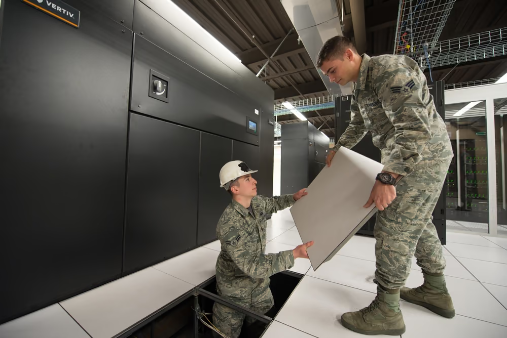
Documentary plate

Cooling upgrades are industrial retrofits

Pipes, pumps, controls, shutdowns, and acceptance work sit behind thermal capacity.

This photograph documents cooling infrastructure work associated with a government high-performance computing environment. It is not presented as a hyperscale commercial AI data center or as evidence of a particular cooling efficiency. Its role is to show the physical nature of the system: thermal capacity is created through installed mechanical equipment, controlled connections, trained work, and testing.

Retrofits are especially demanding because construction occurs around live services and inherited constraints. Teams must establish isolation boundaries, temporary cooling, contamination control, shutdown sequencing, and rollback. New racks may arrive faster than plant modifications, but energizing beyond verified thermal capacity simply moves the schedule risk into throttling or outage. Cooling readiness should be a formal gate for compute acceptance.

Technicians working beside raised-floor panels and computer-room cooling equipment in an HPC data center.

Cooling-system retrofit work in a government high-performance computing context.

Documentary context only; no claim is made that the pictured system represents a hyperscale AI cooling architecture or efficiency benchmark.DVIDS marks the item public domain. It documents an HPC cooling retrofit, not a modern direct-to-chip AI hall. The appearance of U.S. Department of War (DoW) visual information does not imply or constitute DoW endorsement. Individuals' publicity and privacy rights are not waived.U.S. Air Force photo by Paul Shirk, via DVIDS, public domain.Original sourceU.S. government work / public domain

Leak protection is a layered operating system: compatible joints and hoses, controlled installation, pressure testing, accessible isolation, detection placed along credible paths, automatic actions with understood consequences, containment, drainage, response equipment, and trained staff. A detector count does not prove protection if alarms are slow, inaccessible, or mapped to the wrong valve. Audit both nuisance and missed-detection cases, and test whether a local isolation preserves enough cooling elsewhere. Incident records should connect fluid loss, affected equipment, cleanup, downtime, and corrective action.

Spread 12 / Heat rejection and water

Outside the hall

Heat must finally meet the environment

Climate, water strategy, noise, plume, and land shape the last thermal step.

Cooling towers can reject heat efficiently through evaporation but consume water and require treatment. Dry coolers reject heat to air with less direct water consumption but may need more surface, fan energy, or higher coolant temperatures during hot weather. Hybrid systems move between modes. Chillers, thermal storage, geothermal exchange, or heat reuse may serve particular climates and loads, each with its own power, water, maintenance, and permitting implications.

Selection should use hourly weather and workload conditions, not only annual averages. The design must cover extreme heat, smoke or dust, freezing, noise limits, water availability, discharge rules, treatment chemicals, drift, and visible plume where relevant. Heat reuse is valuable only where a nearby demand, temperature level, commercial arrangement, and reliable operating match exist. The atmosphere is part of the cooling circuit even when it is outside the fence.

Report the rejection boundary
  • Equipment mode and design weather condition
  • Site electricity, withdrawals, consumption, and discharge
  • Water source, treatment, season, and local stress context
  • Noise, plume, chemicals, and degraded-mode behavior
Water reporting needs a reconciled balance
MeasureBoundary question
WithdrawalWhat enters from each municipal, surface, groundwater, reclaimed, or stored source?
ConsumptionWhat does not return promptly to the same watershed because of evaporation or incorporation?
DischargeWhere does water leave, with what quality, temperature, timing, and permit condition?
ReuseIs recirculated volume reported separately from new intake and treatment loss?
IntensityWhich IT energy, facility energy, workload, climate period, and operating state form the denominator?

Measurement boundary

WUE needs a definition and a place

A national average cannot describe one facility's local water consequence.

Water usage effectiveness usually relates site water consumption to IT energy, but results depend on cooling architecture, climate, utilization, season, water source, and the precise accounting boundary. LBNL estimated a U.S. average site WUE just over 0.36 liters per kilowatt-hour through 2023. That modeled national average is not a default ratio for every project and should not be applied blindly to a different cooling profile.Claim

Project reporting should separate withdrawal from consumption, potable from reclaimed or other sources, and site use from water associated with electricity generation. Monthly or seasonal values can reveal peaks hidden by annual totals. Local basin conditions and competing uses give the volume meaning. A dry-cooled site may reduce direct water use while increasing electricity demand; the tradeoff belongs in one system boundary.

LBNL estimate of average U.S. data-center site WUE through 2023.
>0.36 L/kWh
Evidence class
estimate
Claim
claim-us-average-wue-2023
Context
A national modeled average; individual facilities vary materially with climate, design, load, and accounting boundary.

Power usage effectiveness divides total facility energy by IT-equipment energy; it does not measure useful computing work, grid emissions, water stress, or embodied impact. The LBNL series below models a U.S. stock average, so it should not be read as measurements from one operator or a guarantee for a new hall. The 2028 endpoints are projections under efficiency assumptions. Compare facilities only after aligning IT-boundary rules, partial load, climate, redundancy state, and treatment of offices, generation, export, and shared campus systems.

Modeled U.S. data-center average PUE

LBNL modeled stock-average PUE for 2014 and 2023, followed by a projected 2028 range under lower- and higher-efficiency cases.
Average PUEPUE ratio
View chart values
Modeled U.S. data-center average PUE — underlying values in PUE ratio
CategoryAverage PUE
2014 modeled1.6 PUE ratio
2023 modeled1.4 PUE ratio
2028 projected low1.15 PUE ratio
2028 projected high1.35 PUE ratio

MODEL BOUNDARY — U.S. data-center stock average; 2028 values are projected endpoints, not observed facility results. PUE excludes workload productivity and full lifecycle impacts.

04

Energize and operate

Connect the campus to generation, grid institutions, flexible controls, maintenance, and measured public obligations.

Spread 13 / Energy and capacity

Power system

A contract does not move electrons

Load requires generation, network delivery, protection, and reliability in the same hours and place.

Annual energy describes megawatt-hours consumed over time. Serving a campus also requires dependable capacity during peak and stressed hours, transmission and distribution paths, voltage support, reserves, protection, and equipment that can tolerate the load shape. A power purchase agreement may finance or attribute generation, but it does not by itself prove that physical supply can reach the site whenever the campus operates.

Supply portfolios can include utility generation, bilateral contracts, renewables, gas turbines or engines, nuclear, geothermal, storage, fuel cells, campus microgrids, and backup generators. Each differs in construction time, fuel or weather dependence, emissions, water, operating role, regulation, and ability to serve continuously. Comparisons should state whether a resource supplies annual energy, accredited capacity, short-duration ride-through, backup, or verified load flexibility.

Energy
Electricity produced or consumed over a period, commonly measured in megawatt-hours.
Capacity
The ability to supply demand at a moment under defined availability and system conditions.
Deliverability
Whether network infrastructure can move power from resources to the load when needed.

This IEA estimate allocates the physical electricity supplying data centers worldwide in 2024; it is not a contractual procurement ledger and the displayed categories do not total one hundred percent because other sources are outside the selected comparison. Geography and hour matter: annual certificates or contracts can differ from the generators serving load at a particular time and place. Use the mix to explain system exposure, then pair it with regional dispatch, marginal effects, new-build timing, transmission, curtailment, storage losses, and contract terms.

Estimated physical supply mix for global data centers in 2024

IEA estimate of selected generation sources physically supplying worldwide data-center electricity demand during 2024.
Physical supply sharePercent of electricity supply
View chart values
Estimated physical supply mix for global data centers in 2024 — underlying values in Percent of electricity supply
CategoryPhysical supply share
Coal30% Percent of electricity supply
Renewables27% Percent of electricity supply
Natural gas26% Percent of electricity supply
Nuclear15% Percent of electricity supply

GLOBAL PHYSICAL-SUPPLY ESTIMATE — selected categories sum to 98%; not a contractual clean-energy claim, regional mix, marginal-emissions estimate, or AI-only allocation.

Scale + uncertainty

Forecasts are planning ranges, not destinies

Demand depends on deployment, utilization, efficiency, and whether power constraints are resolved.

The IEA's 2025 report estimates that data centers used about 415 terawatt-hours worldwide in 2024 and projects about 945 terawatt-hours in its 2030 base case. LBNL's December 2024 report placed U.S. 2028 demand between 325 and 580 terawatt-hours; its June 2026 update instead models a 649-terawatt-hour U.S. Reference Case for 2030 with 521-to-843-terawatt-hour compounded-uncertainty bounds. The later publication uses a different horizon and updated model rather than explicitly superseding the older 2028 series, so both remain visible with their publication dates instead of being blended into one forecast.ClaimClaimClaimClaim

Their shared implication is planning pressure, not inevitability. Hardware efficiency, workload demand, utilization, deployment pace, geographic shifts, and delayed energization can change the result. Grid planners and developers need scenarios that preserve those drivers and show their effect on substations, transmission, generation, and customer costs. The correct response to uncertainty is staged evidence and flexible design, not false precision.

IEA estimate for global data-center electricity use in 2024.
415 TWh
Evidence class
estimate
Claim
claim-global-dc-electricity-2024
Context
A modeled historical estimate, not a directly metered global total.
IEA base-case projection for global data-center electricity use in 2030.
945 TWh
Evidence class
projection
Claim
claim-global-dc-electricity-2030
Context
A scenario dependent on deployment, utilization, and efficiency assumptions.
An energy resource must satisfy more than annual volume
AttributeQuestion for the campus case
CapacityCan the system meet coincident peak demand after outages, derating, and reserves?
EnergyCan it sustain the required output over the relevant day, season, and fuel condition?
DeliverabilityAre transmission, distribution, protection, and interconnection available when needed?
OperabilityCan ramps, voltage, frequency, inertia, storage duration, and restart needs be managed?
ExternalitiesWho experiences emissions, land, water, safety, waste, price, and reliability effects?

Spread 14 / Queue and flexibility

Interconnection

Generation and load follow institutional paths

Studies determine which upgrades and operating limits connect a project to the network.

New generation commonly enters interconnection studies that assess network impacts and identify upgrades. In the United States, FERC Order No. 2023 requires cluster studies, stronger project-readiness requirements, and transmission-provider delay penalties for generator interconnection. The rule is effective, but FERC's chair said in June 2026 that transmission-provider compliance remained incomplete, so it is not evidence of one universally implemented schedule.ClaimClaim

Large-load requests have their own utility and regional processes. In June 2026, FERC opened targeted proceedings for six RTOs and ISOs to justify or reform practices spanning flexible service, cost allocation, and co-location. Those show-cause orders start regional tariff work; they do not establish a completed national connection rule. Developers must still align load ramp, substation work, generation milestones, tariffs, security, and commissioning.Claim

Queue boundary: An interconnection position is a study process, not delivered capacity. Read the milestones, upgrade scope, cost responsibility, dependencies, and withdrawal risk.

LBNL's queue snapshot records proposed U.S. generation and storage seeking transmission interconnection at the end of 2024. It is a development pipeline, not delivered capacity: projects differ in maturity, location, commercial viability, network upgrades, and probability of completion. Generation and storage also are unlike quantities, so the bars should not be added. A data-center plan must identify which resource, network work, study position, cost responsibility, operating date, and contractual right can actually serve its node.

U.S. interconnection-queue capacity at year-end 2024

LBNL compilation of proposed generation and storage capacity actively seeking transmission interconnection in U.S. queues.
Queued capacityGW
View chart values
U.S. interconnection-queue capacity at year-end 2024 — underlying values in GW
CategoryQueued capacity
Generation1,400 GW
Storage890 GW

PIPELINE, NOT SUPPLY — year-end 2024 proposed capacity; storage and generation are different resources and must not be summed as equivalent dependable output.

Flexible load

Compute can respond—within limits

Power capping and workload movement become grid resources only when verified and contracted.

Some workloads can shift in time, move between regions, slow through power caps, or pause after a checkpoint. Batteries can bridge short events, and staged energization can align growth with network readiness. Other workloads have strict response deadlines, data-locality requirements, safety constraints, or expensive interruption costs. The flexible portion is therefore smaller and more conditional than total nameplate load.

To count flexibility, operators need telemetry, control authority, response time, duration, recovery behavior, and an agreement defining when action is called. LBNL's maturity model treats evaluation, measurement and verification plus enabling data infrastructure as distinct capabilities. Tests must show that a reduction at the grid meter persists without shifting the problem into cooling, backup emissions, or later rebound peaks.Claim

Measurement is counterfactual as well as physical. FERC-hosted guidance compares observed load with an estimated baseline, requires uncertainty to be characterized, and treats post-event rebound separately. PJM's current regional rules add product-specific registration, interval-meter or approved submeter data, notification, and settlement. DOE's 2026 monitoring analysis further distinguishes waveform telemetry for high-frequency AI-load oscillations from billing-grade meter evidence.ClaimClaimClaim

A primary field demonstration provides a deliberately narrow measured case: one 256-GPU cluster in a commercial Phoenix facility reduced cluster power by twenty-five percent for three hours while maintaining the study's defined quality-of-service guarantees. It does not establish whole-facility flexible megawatts, availability for other workloads, fleet-scale recurrence, or a settled market resource.Claim

Make flexibility real
  1. Classify— Identify workloads that can shift, cap, checkpoint, or pause.
  2. Control— Connect grid signal to safe software and facility actions.
  3. Verify— Measure response, duration, rebound, and service impact.
  4. Contract— Define availability, notice, compensation, and nonperformance.
A flexible-load offer needs enforceable operating detail
  • Define the controllable boundary, maximum change, response time, duration, recovery ramp, notice, and unavailable periods.
  • Separate workload migration, checkpointing, battery discharge, generator use, and true demand reduction because their system effects differ.
  • Protect life safety, cooling minimums, data integrity, equipment warranties, and worker procedures during dispatch and restoration.
  • Specify telemetry, baseline, verification, performance remedies, override authority, and treatment of failed communications.
  • Show who receives the benefit and whether network costs, emissions, or reliability risk move to other customers or communities.

Spread 15 / Operate the compact

Operations

The campus is never finished

Maintenance, refresh, capacity, and compliance continue after commissioning.

Operations integrates facility control, IT monitoring, security, maintenance, spares, incident response, environmental obligations, utility communication, and change management. Filters load, batteries age, water chemistry shifts, firmware changes, and equipment enters end of support. Deferred maintenance can preserve a short-term uptime metric while eroding the next failure response. Every asset needs ownership, condition evidence, a safe maintenance state, and a replacement path.

Compute refresh cycles can be shorter than building life, so each new generation tests the original envelopes for weight, power, coolant, network, and heat rejection. Teams should preserve as-built records and compare proposed equipment against measured operating headroom. Decommissioned electronics, batteries, refrigerants, generators, and construction materials need secure reuse, recycling, or disposal routes. Lifecycle planning is part of site capacity, not an afterthought.

The operating ledger
  • Measured IT and facility load, efficiency, water, and emissions
  • Available electrical, thermal, network, and physical headroom
  • Maintenance condition, spares, alarms, incidents, and exercises
  • Permit obligations, community commitments, refresh, and end-of-life routes
The operating compact assigns outcomes, not just tasks
DomainAccountable evidence
SafetyHazard register, permits to work, drills, incidents, corrective action, and responder interface
ReliabilityOperating limits, maintenance basis, spares, tests, event reviews, and capacity state
OT and securityAsset ownership, access, configuration, patch risk, backups, monitoring, and recovery exercise
EnvironmentMetered boundary, permit compliance, releases, water and waste records, and public reporting
PeopleStaffing model, competencies, fatigue controls, contractor governance, handoffs, and succession

Handoff

A plant operates inside a public compact

Power, water, noise, cost, tax, jobs, and risk cross the fence in both directions.

The campus depends on utilities, public infrastructure, emergency services, workforce, water systems, and regulatory legitimacy. Its effects can include construction traffic, equipment noise, tax revenue, temporary and permanent employment, emissions, water use, and utility upgrades whose costs must be allocated. These outcomes differ by project and cannot be inferred from a global demand trend or a generic jobs multiplier.

The responsible handoff from Plant to Permission is a dated set of project facts: physical status, utility obligations, permit conditions, operating metrics, forecast ranges, risk bearers, and channels for community input. Public claims should distinguish measured operation from forecast and vendor specification. The buildout earns durability when the industrial system remains legible to the people who operate, regulate, finance, and live beside it.

Final boundary: A facility is not fully described by megawatts. State what is built, energized, measured, permitted, promised, uncertain, and paid for—and by whom.
Keep change inside the design and permission envelope
  1. Propose— State the need, affected assets, workload, hazard, permit, security, and community boundaries.
  2. Review— Bring engineering, operations, safety, OT, environmental, vendor, and utility owners together.
  3. Authorize— Approve design, isolation, test, rollback, notification, training, and evidence requirements.
  4. Execute— Control configuration, temporary states, concurrent work, deviations, and real-time authority.
  5. Close— Validate performance, update records and spares, resolve deficiencies, and monitor emergent effects.

Behind the claim

Evidence, in context.

Opening the evidence record…